
Contact angle measuring instrument for nano coating

A nano-coating and contact angle technology, applied in measuring devices, instruments, scientific instruments, etc., can solve the problems of low practicability, inconvenient operation and use, unfavorable contact angle, etc. Effect

Pending Publication Date: 2021-02-12
SUZHOU SUNSHINE LASER & ELECTRONICS TECH CO LTD
View PDF0 Cites 0 Cited by
  • Summary
  • Abstract
  • Description
  • Claims
  • Application Information

AI Technical Summary

Problems solved by technology

[0004] 1. When the existing contact angle measuring instrument is measuring, because the fixed angle of the camera used for shooting cannot be adjusted, there are certain requirements for the position, height and distance of the light source and the droplet. It takes a lot of time to adjust the position of the light source and the droplet during the measurement, which is not easy to operate and use, and has low practicability;
[0005] 2. When the existing contact angle measuring instrument releases droplets, it generally uses manual manual pressing of the syringe or pushes the syringe with air pressure to release the droplet. Manually pressing the syringe is not easy to control the force, and pushing the syringe with air pressure can easily cause liquid droplets in the syringe. Excessive release, resulting in the inability to form a complete droplet on the test surface, which is not conducive to the formation of the contact angle;

Method used


Image

  • Contact angle measuring instrument for nano coating
  • Contact angle measuring instrument for nano coating
  • Contact angle measuring instrument for nano coating

Examples


Embodiment Construction

[0021] The following will clearly and completely describe the technical solutions in the embodiments of the present invention with reference to the accompanying drawings in the embodiments of the present invention. Obviously, the described embodiments are only some, not all, embodiments of the present invention. Based on the embodiments of the present invention, all other embodiments obtained by persons of ordinary skill in the art without making creative efforts belong to the protection scope of the present invention.

[0022] In the description of the present invention, it should be noted that the terms "upper", "lower", "inner", "outer", "front end", "rear end", "both ends", "one end", "another end" The orientation or positional relationship indicated by etc. is based on the orientation or positional relationship shown in the drawings, and is only for the convenience of describing the present invention and simplifying the description, rather than indicating or implying that ...


PUM


Abstract

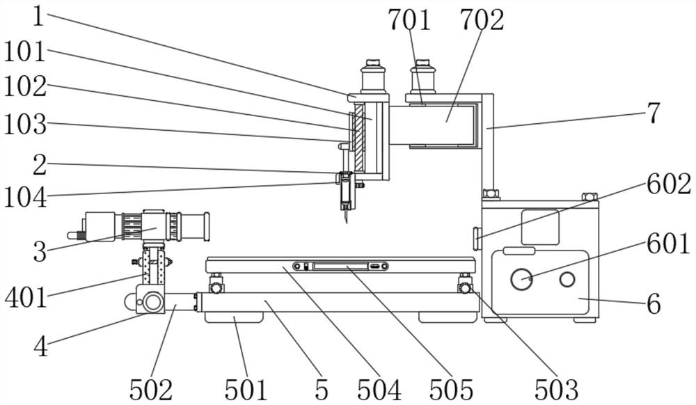
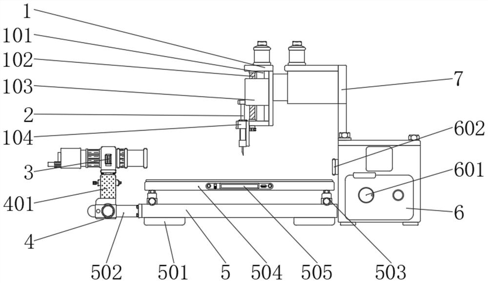
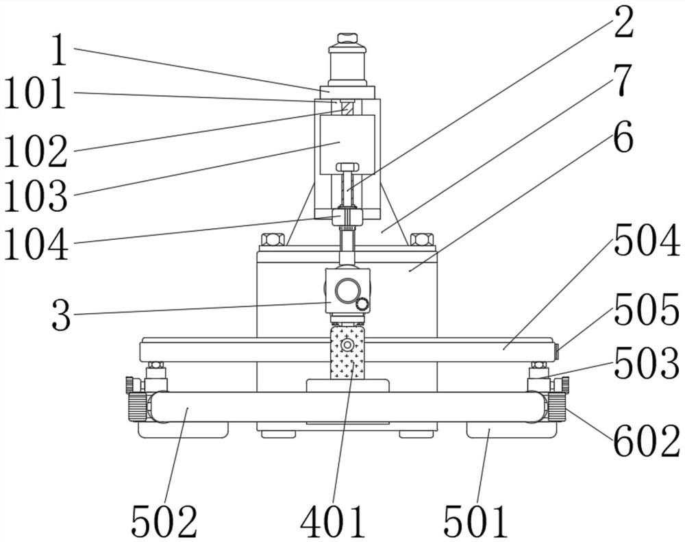
The invention discloses a contact angle measuring instrument for a nano coating. The instrument comprises a fixing frame, a screw rod adjusting mechanism, a test chassis and a CCD camera. A steel pipeis installed on one side of the test chassis through bolts, the screw rod adjusting mechanism is movably installed on the outer side of the steel pipe, a screw rod is installed in the screw rod adjusting mechanism, and an adjusting seat is mounted on the outer side of the screw rod through a thread structure. The screw rod adjusting mechanism is installed on the outer side of the steel pipe, thescrew rod can be driven to rotate through rotation of a threaded sleeve, the threaded structure on the inner side of the adjusting seat is meshed with threads on the surface of the screw rod , the left-right position of the adjusting seat can be adjusted, and the clamping tightness of the pipe sleeve to the steel pipe can be controlled by rotating an adjusting knob; and the front-back distance ofthe screw rod adjusting mechanism can be adjusted conveniently, the position of an LED spotlight can be adjusted to a position suitable for measurement conveniently, and the practicability of the device is greatly improved.

Description

technical field [0001] The invention relates to the technical field of contact angle measuring instruments, in particular to a contact angle measuring instrument for nano coatings. Background technique [0002] Nano-coating has the function of enhancing the lubrication degree of solid surface. The solid surface using nano-coating can have the characteristics of hydrophobic and oleophobic, which is beneficial to keep the solid surface clean. The contact angle refers to the drop of a liquid drop on a solid horizontal plane. , at the solid-liquid-gas three-phase junction point on the solid surface, the angle formed when the two tangent lines of the gas-liquid interface and the solid-liquid interface sandwich the liquid phase, the contact angle tester is mainly used to measure the liquid The contact angle of solid, that is, the wettability of liquid to solid, can measure the contact angle of various liquids to various materials. In order to measure the contact angle of the surfa...

Claims


Application Information

Patent Timeline
Patent Type & Authority Applications(China)
IPC IPC(8): G01N13/02F21S8/00F21V17/12F21V14/02F21Y115/10
CPCF21S8/00F21V14/02F21V17/12F21Y2115/10G01N13/02G01N2013/0208G01N2013/0241
Inventor 王荣郭学亮
Owner SUZHOU SUNSHINE LASER & ELECTRONICS TECH CO LTD
Learn More