
Rapid air suction sampling device for air detection

A technology of air detection and sampling devices, applied in the direction of sampling devices, etc., to achieve the effect of high accuracy

Inactive Publication Date: 2021-02-12
北京鼎翰建筑有限公司
View PDF1 Cites 3 Cited by
  • Summary
  • Abstract
  • Description
  • Claims
  • Application Information

AI Technical Summary

Problems solved by technology

[0003] Air detection mainly detects components of the air, outdoor air detection mainly detects air pollution caused by industry, and indoor air detection mainly detects harmful substances released by decoration materials or furniture; CN211148213U discloses an air detection The rapid aspirating sampling device comprises an aspirating cylinder, an air pumping mechanism is arranged inside the aspirating cylinder, a through hole is opened at one end of the aspirating cylinder close to the aspirating mechanism, and the aspirating cylinder is far away from the aspirating mechanism One end of the ventilating mechanism is provided with a ventilating mechanism, and the ventilating mechanism includes an movable slot horizontally opened on the end of the suction cylinder away from the pumping mechanism. The interior of the movable slot is equipped with a rotating shaft. The matching baffle, the bottom of the baffle and the suction cylinder are provided with a plurality of suction holes; the sampling device can only achieve one sampling in a single operation, and the sampling tube needs to be replaced after sampling, and multiple suction holes cannot be continuously performed. multiple sampling jobs at a location

Method used


Image

  • Rapid air suction sampling device for air detection
  • Rapid air suction sampling device for air detection
  • Rapid air suction sampling device for air detection

Examples


Embodiment Construction

[0025] The following will clearly and completely describe the technical solutions in the embodiments of the present invention with reference to the accompanying drawings in the embodiments of the present invention. Obviously, the described embodiments are only some, not all, embodiments of the present invention.

[0026] In describing the present invention, it should be understood that the terms "upper", "lower", "front", "rear", "left", "right", "top", "bottom", "inner", " The orientation or positional relationship indicated by "outside", etc. is based on the orientation or positional relationship shown in the drawings, and is only for the convenience of describing the present invention and simplifying the description, rather than indicating or implying that the referred device or element must have a specific orientation, so as to Specific orientation configurations and operations, therefore, are not to be construed as limitations on the invention.

[0027] refer to Figure ...


PUM


Abstract

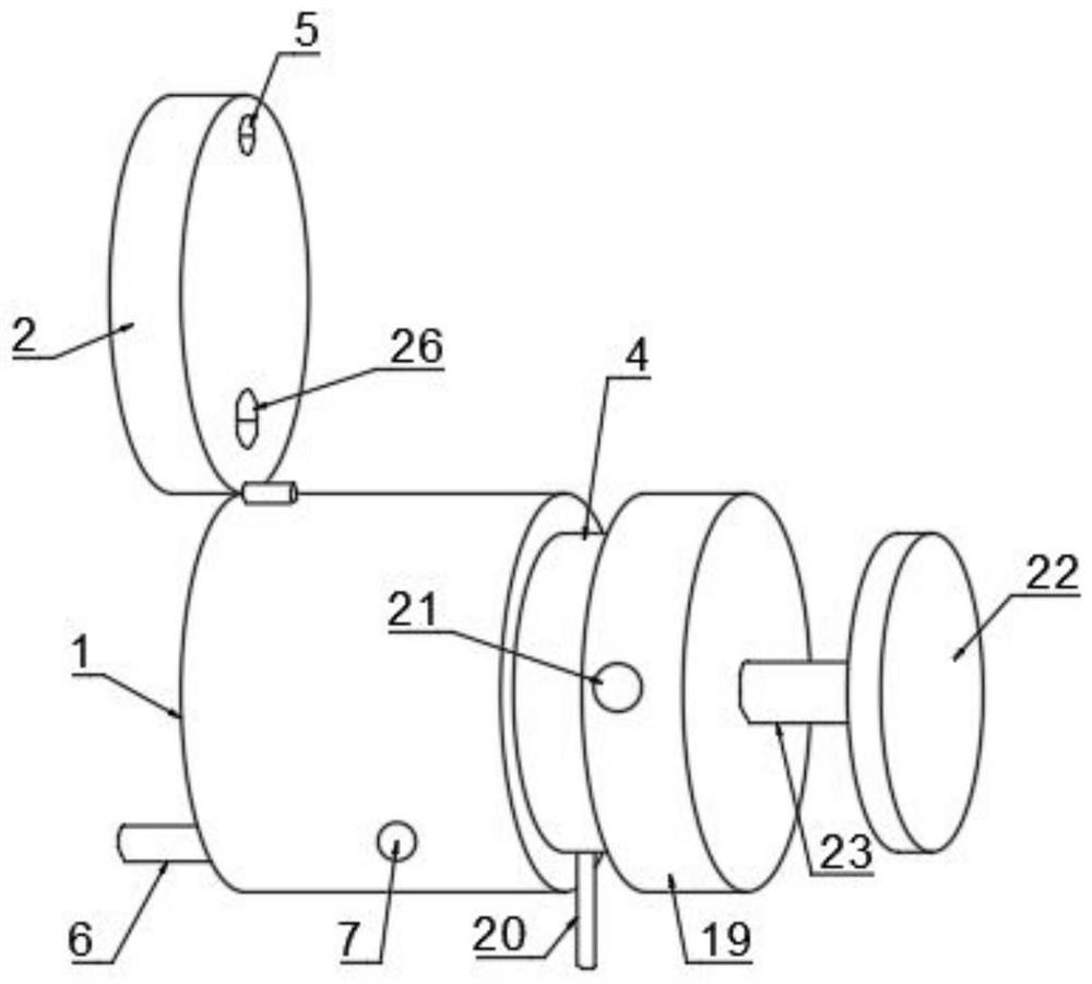
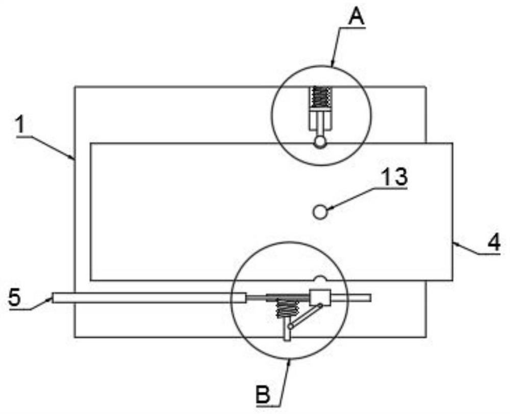
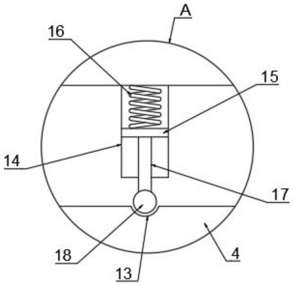
The invention discloses a rapid air suction sampling device for air detection, wherein the rapid air suction sampling device comprises a shell; a cover plate is rotatably connected to the left end ofthe shell, a fixing opening is formed in the inner side wall of the cover plate, a connecting mechanism is arranged between the shell and the fixing opening, an inner barrel is rotatably connected into the shell, and a plurality of sampling pipes are uniformly inserted into the inner barrel; an air inlet is formed in the cover plate in a penetrating mode, the right end of the shell is fixedly connected with a connecting end through a connecting rod, an inserting groove is formed in the end of the connecting end, the right end of the inner barrel is inserted into the inserting groove, and an air outlet matched with the air inlet in size and position is formed in the inner wall of the inserting groove. Switching of the sampling pipes communicating with the air inlet and the air outlet is achieved through rotation of the inner barrel, residual gas is discharged through staggering of check blocks and through openings in the rotating process of the inner barrel, repeated sampling work is achieved through rotation of the inner barrel, and the problem that repeated sampling is complex when sampling pipes are replaced traditionally is solved.

Description

technical field [0001] The invention relates to the technical field of air detection, in particular to a fast suction sampling device for air detection. Background technique [0002] Air is the "living gas" that we breathe every day. It covers the surface of the earth in layers. It is transparent, colorless and odorless. It is mainly composed of nitrogen and oxygen, which has an important impact on human survival and production. Oxygen in the air is important for A must for all aerobic organisms. Air is colorless and odorless in its natural state. [0003] Air detection mainly detects components of the air, outdoor air detection mainly detects air pollution caused by industry, and indoor air detection mainly detects harmful substances released by decoration materials or furniture; CN211148213U discloses an air detection The rapid aspirating sampling device comprises an aspirating cylinder, an air pumping mechanism is arranged inside the aspirating cylinder, a through hole ...

Claims


Application Information

Patent Timeline
Patent Type & Authority Applications(China)
IPC IPC(8): G01N1/24
CPCG01N1/24
Inventor 李建川
Owner 北京鼎翰建筑有限公司
Learn More