
Multi-split system and control method thereof

A multi-connected system and control method technology, applied in refrigerators, refrigeration components, mechanical equipment, etc., can solve problems such as uneven distribution of flat tubes, reduced heat exchange efficiency, and inconsistent amounts of liquid refrigerants

Pending Publication Date: 2021-02-12
GREE ELECTRIC APPLIANCES INC
View PDF7 Cites 2 Cited by
  • Summary
  • Abstract
  • Description
  • Claims
  • Application Information

AI Technical Summary

Problems solved by technology

With the continuous promotion and upgrading of aluminum micro-channel heat exchanger technology, micro-channel heat exchangers have begun to be used in central air-conditioning and other multi-connected fields. Since the operating power of multi-connected devices is generally above 5 horsepower, the heat exchanger area is required to be relatively small. Large, the number and length of the total flat tubes in the microchannel increase, and often a flow path of the microchannel heat exchanger is connected in parallel with multiple flat tubes to form a process, so there will be uneven distribution between the flat tubes in the flow path
[0003] During the heating operation, the liquid refrigerant exists in a gas-liquid two-phase state after being throttled by the electronic expansion valve. Therefore, when it reaches the inlet of a flat tube in a flow path, it is affected by gravity, the gas refrigerant will go up, and the liquid refrigerant will go down. Go, the amount of liquid refrigerant distributed by the upper and lower flat tubes is inconsistent, resulting in uneven distribution, which in turn will cause uneven temperature distribution of the heat exchanger and reduce heat exchange efficiency

Method used


Image

  • Multi-split system and control method thereof
  • Multi-split system and control method thereof
  • Multi-split system and control method thereof

Examples


Embodiment Construction

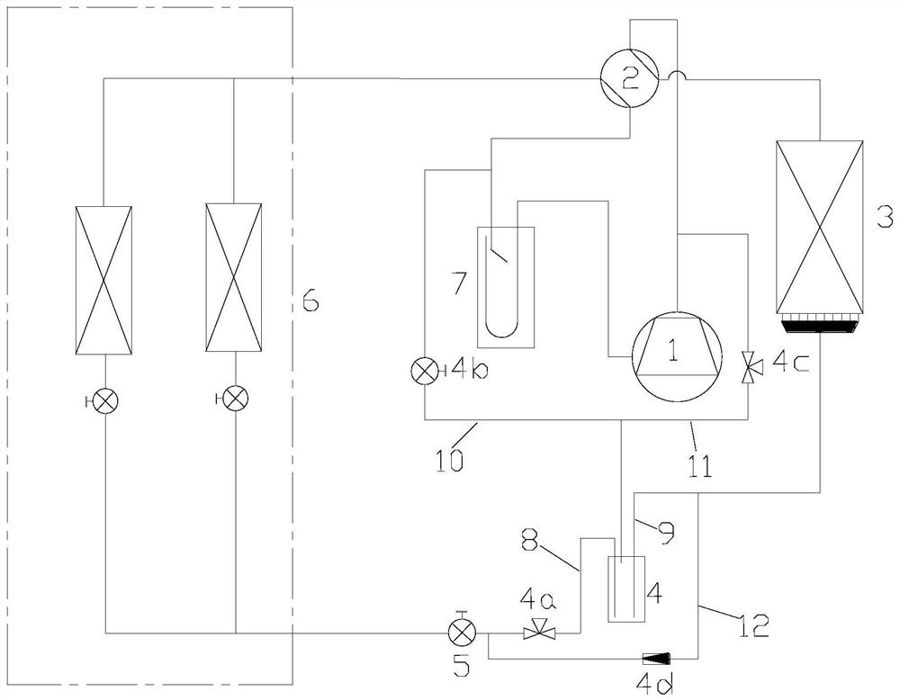
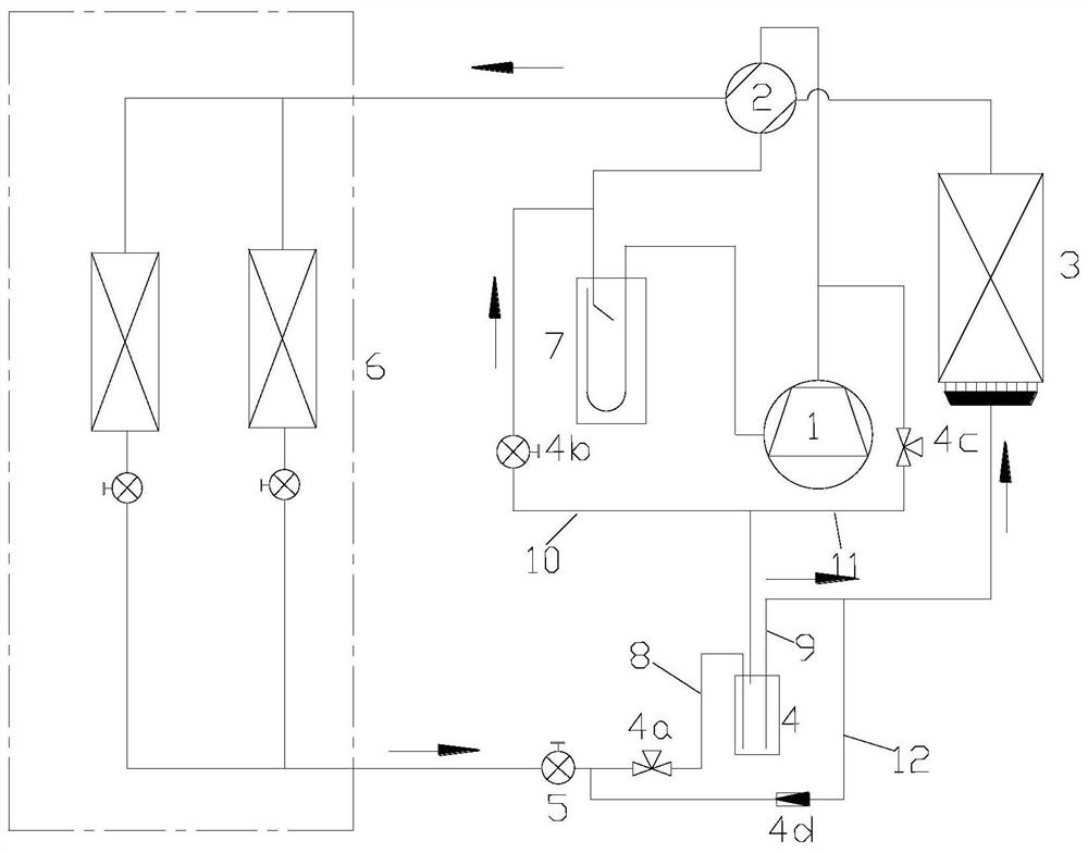
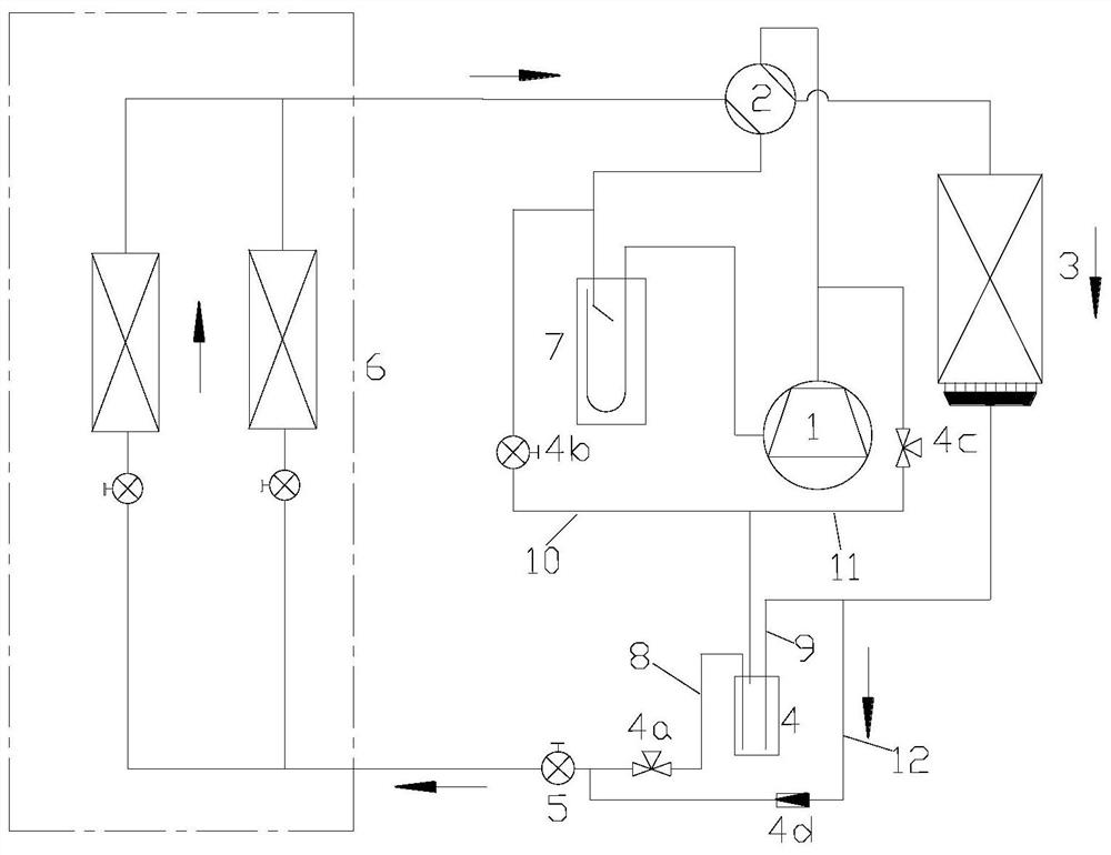
[0039] see in conjunction Figure 1 to Figure 5 As shown, according to the embodiment of the present application, the multi-line system includes a compressor 1, an outdoor heat exchanger, a throttling device 5 and an indoor unit 6, the outdoor heat exchanger includes a microchannel heat exchanger 3, and the throttling device 5 is located in the microchannel On the pipeline between the channel heat exchanger 3 and the indoor unit 6, on the pipeline between the throttling device 5 and the microchannel heat exchanger 3, a liquid storage tank 4 is arranged, and the liquid storage tank 4 is connected with a first liquid pipe 8, The second liquid pipe 9 and the first air pipe 10, the first air pipe 10 is connected to the suction port of the compressor 1, the first liquid pipe 8 is connected to the throttling device 5, and the second liquid pipe 9 is connected to the microchannel heat exchanger 3 .

[0040] The multi-connected system is provided with a liquid storage tank on the pip...


PUM


Abstract

The invention provides a multi-split system and a control method thereof. The multi-split system comprises a compressor (1), an outdoor heat exchanger, a throttling device (5) and an indoor unit (6),wherein the outdoor heat exchanger comprises a micro-channel heat exchanger (3); the throttling device (5) is located on a pipeline between the micro-channel heat exchanger (3) and the indoor unit (6); a liquid storage tank (4) is arranged on a pipeline between the throttling device (5) and the micro-channel heat exchanger (3); the liquid storage tank (4) is connected to a first liquid pipe (8), asecond liquid pipe (9) and a first air pipe (10); the first air pipe (10) is connected to an air suction port of the compressor (1); the first liquid pipe (8) is connected to the throttling device (5); and the second liquid pipe (9) is connected to the micro-channel heat exchanger (3). According to the multi-split system, the refrigerant distribution uniformity of the micro-channel heat exchangercan be improved, and the heat exchange efficiency of the heat exchanger is improved.

Description

technical field [0001] The present application relates to the technical field of air conditioning, in particular to a multi-connected system and a control method thereof. Background technique [0002] Micro-channel heat exchangers have higher heat transfer coefficients than common copper tube finned tube heat exchangers, and are relatively low in cost. They are the best substitutes for finned copper tubes and are widely used in household air conditioners and water heaters. With the continuous promotion and upgrading of aluminum micro-channel heat exchanger technology, micro-channel heat exchangers have begun to be used in central air-conditioning and other multi-connected fields. Since the operating power of multi-connected devices is generally above 5 horsepower, the heat exchanger area is required to be relatively small. Larger, the number and length of the total flat tubes in the microchannel increase, and often a flow path of the microchannel heat exchanger is connected ...

Claims


Application Information

Patent Timeline
IPC IPC(8): F25B41/30F25B43/00F28F9/00
CPCF25B43/006F28F9/00F28F2260/02Y02B30/70
Inventor 杨玉生胡强王永立顾思忠徐如好
Owner GREE ELECTRIC APPLIANCES INC
Learn More