Fluid control device

A fluid control device and control valve technology, which is used in liquid variable capacity machinery, variable capacity pump components, and pumps with flexible working elements, etc., which can solve the problems of many sealing points, insufficient compact structure, and large space occupation, etc. problems, to achieve the effect of reducing the sealing position, compact structure and improving reliability

Pending Publication Date: 2021-02-12
广东诗奇制造有限公司
View PDF0 Cites 0 Cited by
  • Summary
  • Abstract
  • Description
  • Claims
  • Application Information

AI Technical Summary

Problems solved by technology

[0003] However, the general disadvantage of the existing piezoelectric pumps is that when the piezoelectric pump is connected to the control valve, the struct

Method used


Image

  • Fluid control device
  • Fluid control device
  • Fluid control device

Examples


Embodiment approach

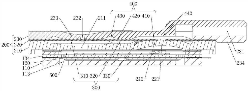
[0101] Surfaces of the first protruding portion 212 and the second protruding portion 233 are arc-shaped. Such arrangement can make the sealing connection between the diaphragm 220 and the first protruding portion 212 tighter in a natural state, and the sealing connection between the diaphragm 220 and the second protruding portion 233 is also tighter.

[0102] As a further preferred embodiment:

[0103] The air outlet hole 231 is disposed in the air outlet pipe 234 of the valve body upper shell 230, and the air outlet pipe 234 extends along the horizontal direction; thus, the air outlet pipe 234 is arranged in the horizontal direction to further compress the space of the fluid control device in the height direction. At the same time, in order to further compress the space in the height direction, the base plate 110 is provided with an air-introduction groove extending in the horizontal direction, and the two ends of the air-induction groove are respectively connected to the op...


PUM

PropertyMeasurementUnit
Spacingaaaaaaaaaa

Abstract

The invention discloses a fluid control device. The fluid control device comprises a piezoelectric pump and a control valve. The piezoelectric pump comprises a base plate with an opening, a flexible plate with a suction hole and a piezoelectric actuator with a vibrating plate and a piezoelectric element. The base plate, the flexible plate and the piezoelectric actuator are sequentially arranged inan overlapped mode. The control valve comprises a valve body lower shell, a diaphragm and a valve body upper shell which are sequentially arranged in an overlapped mode. The valve body lower shell isprovided with an air inlet hole, and the valve body upper shell is provided with an air outlet hole and an exhaust hole. The diaphragm and the valve body lower shell form a first valve chamber, the diaphragm and the valve body upper shell form a second valve chamber, and the diaphragm is provided with a through hole capable of communicating the first valve chamber with the second valve chamber. The valve body lower shell is provided with a first protruding part, and the part, located around the through hole, of the diaphragm abuts against the first protruding part. The valve body upper shellis provided with a second protruding part, the exhaust hole is formed in the second protruding part, and the part, located around the exhaust hole, of the diaphragm abuts against the second protrudingpart. The valve body lower shell covers the piezoelectric actuator in a sealing mode to form a pump chamber. The fluid control device is more compact in structure, and the positions needing to be sealed are reduced.

Description

technical field [0001] The present invention relates to the technical field of fluid control devices, in particular to fluid control devices. Background technique [0002] In the prior art, micro air pumps are classified according to their working principles: motor diaphragm type, electromagnetic type, impeller type, piston type, piezoelectric ceramic type, etc. Among them, motor diaphragm type, electromagnetic type, impeller type, and piston type air pumps are driven by motors or electromagnets, etc., and the size cannot be made small, so the size of the entire air pump is also relatively large. Piezoelectric ceramic air pumps on the domestic market have the defects of small air volume and low pump air pressure due to the fixed constraints around the piezoelectric ceramic elements, and the vibration amplitude of the piezoelectric ceramic elements is restricted after being energized. That is to say, each existing air pump has advantages and disadvantages. [0003] However,...

Claims


Application Information

Patent Timeline
IPC IPC(8): F04B45/047F04B39/10F04B39/12F04B39/00
CPCF04B39/00F04B39/10F04B39/123F04B45/047
Inventor 戚付生刘杰伍开贵王泽俊冯涛胡凯
Owner 广东诗奇制造有限公司
Why Eureka
Try Eureka