
Orienting device for drilling of tunnel arch frame feet-lock bolt

A technology of locking foot bolt and directional device, which is applied in directional drilling, bolt installation, earthwork drilling and mining, etc. It can solve the problem of difficult control of the entry angle of the locking foot bolt, failure of the initial support function of the tunnel, and failure of the locking foot bolt. To avoid problems such as weakening of the effect, to avoid construction hazards, to achieve good adjustment effects, and to improve construction accuracy

Pending Publication Date: 2021-02-12
中铁二十三局集团第四工程有限公司
View PDF0 Cites 1 Cited by
  • Summary
  • Abstract
  • Description
  • Claims
  • Application Information

AI Technical Summary

Problems solved by technology

[0003] The purpose of the present invention is to: in the prior art, it is difficult to control the driving angle of the lock-foot bolt, and the angle deviation will greatly weaken the function of the lock-foot bolt. To solve the problems of major quality and safety accidents, provide a directional device for tunnel arch locking foot bolt drilling

Method used


Image

  • Orienting device for drilling of tunnel arch frame feet-lock bolt
  • Orienting device for drilling of tunnel arch frame feet-lock bolt
  • Orienting device for drilling of tunnel arch frame feet-lock bolt

Examples


Embodiment 1

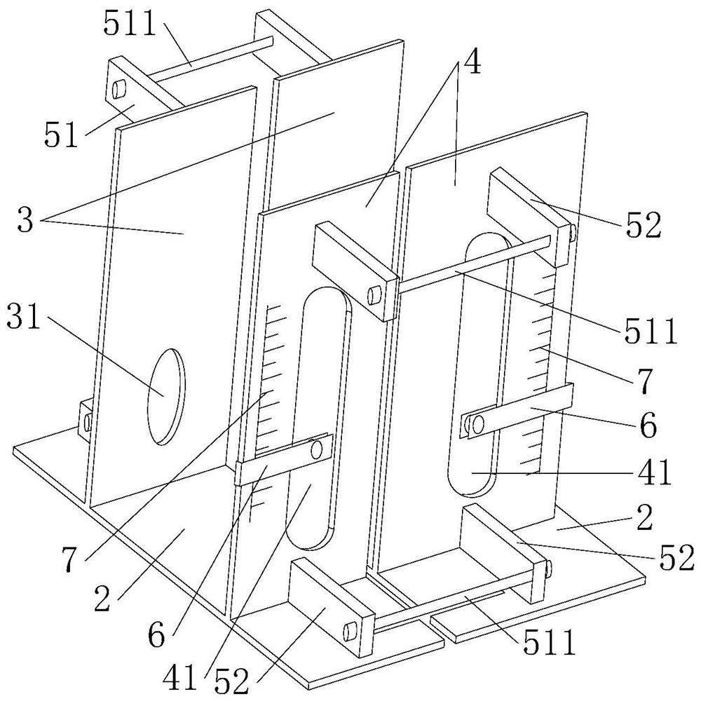
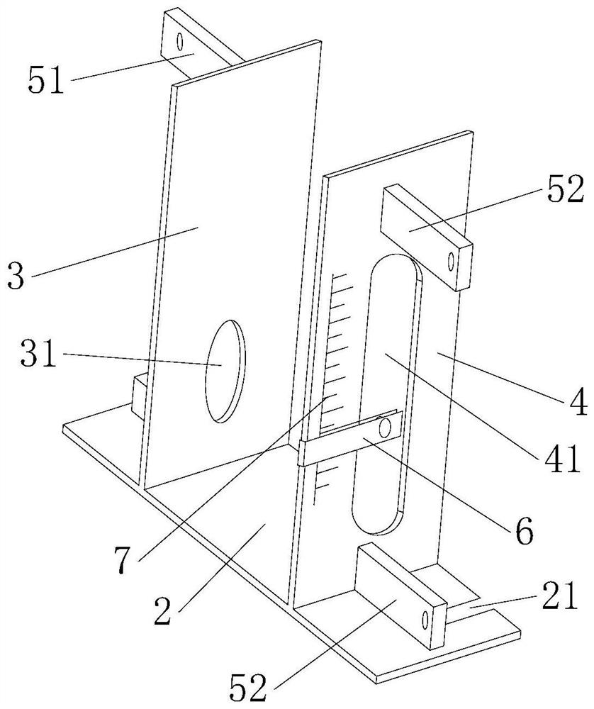
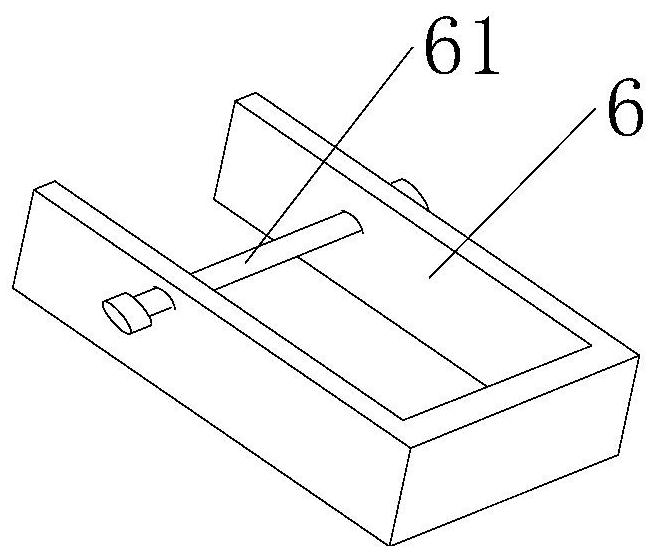
[0029] This embodiment provides an orienting device for drilling anchor rods of locking feet of tunnel arches, see Figure 1-4 , including two directional structures, the two directional structures are used to be oppositely arranged on both sides of the feet of the arch 1, the two directional structures can be detachably connected to the arch 1, and the directional structures include a base 2. The base 2 is provided with a first orientation plate 3 and a second orientation plate 4, the first orientation plate 3 is provided with a first positioning hole 31, and the second orientation plate 4 is provided with a second positioning The hole 41 , the first positioning hole 31 and the second positioning hole 41 of the same orientation structure are used to pass the drill rod 8 and adjust the angle of the drill rod 8 .

[0030] In this example, if Figure 4 As shown, the arch 1 is an I-shaped steel structure. The orientation structure is as figure 2 As shown, it includes a base 2...


PUM


Abstract

The invention provides an orienting device for drilling of a tunnel arch frame feet-lock bolt. The orienting device comprises two orienting structures, wherein the two orienting structures are used for being oppositely arranged on the two sides of the foot part of an arch frame and are detachably connected to the arch frame, each orienting structure comprises a base, a first orienting plate and asecond orienting plate are arranged on each base, a first positioning hole is formed in each first orienting plate, a second positioning hole is formed in each second orienting plate, and the first positioning hole and the second positioning hole of the same orienting structure are used for allowing a drill rod to penetrate through and adjusting the angle of the drill rod. The drilling direction of the drill rod can be adjusted and controlled through the first positioning holes and the second positioning holes, then the direction of the feet-lock bolt is controlled, angle deviation existing inconstruction of the feet-lock bolt is avoided, the construction quality of the feet-lock bolt is guaranteed, then the supporting capacity of the feet-lock bolt is guaranteed, and tunnel constructiondangers are avoided. Meanwhile, the orienting device is detachably connected to the arch frame, can be repeatedly used and is convenient to construct.

Description

technical field [0001] The invention relates to the technical field of tunnel arch lock foot bolt construction technology, in particular to an orienting device for drilling tunnel arch lock foot bolt holes. Background technique [0002] In the tunnel excavation and support process of highways, railways, underground water diversion tunnels, etc., there are often high requirements for the safety, construction quality and appearance of the construction process. However, tunnel excavation in an environment with poor surrounding rock quality requires the use of tunnel bolt technology to support the excavated tunnel. Lock foot bolt technology is widely used in tunnel construction. It refers to the process of fixing the foot of the arch frame through the anchor bolt after the excavation of the upper steps of the tunnel is completed and the arch support is erected, and the fixing needs to be symmetrically fixed on both sides of the foot of the arch frame. The main function of the l...

Claims


Application Information

Patent Timeline
Patent Type & Authority Applications(China)
IPC IPC(8): E21B7/04E21B47/02E21D20/00
CPCE21B7/04E21B47/02E21D20/003
Inventor 张瑞龙刘长林盛怀猛李作军张玉山王云鹏朱毓芳张权威邵万斌曾勇霖
Owner 中铁二十三局集团第四工程有限公司
Learn More