Printing machine with flexographic printing head

A printing head and printing machine technology, applied to printing machines, rotary printing machines, rotary printing machines, etc., can solve the problems of inconvenient adding ink, reduce device compatibility, and reduce the service life of printing machines, so as to increase convenience and improve Compatibility, the effect of expanding the application range

Inactive Publication Date: 2021-02-12
淮南雪魔数码科技有限公司
View PDF0 Cites 1 Cited by
  • Summary
  • Abstract
  • Description
  • Claims
  • Application Information

AI Technical Summary

Problems solved by technology

[0003] However, the existing printing machine with flexographic printing head cannot adjust the height, which is not conducive to connecting with various processing machinery to form an assembly line, which reduces the compatibility of the device and narrows the application range of the device. Printing machines with flexographic printing heads cannot realize quick installation and disassembly functions, which is not conducive to improving the post-maintenance efficiency of printing machines with flexographic printing heads, and increases the maintenance cost of printing machines with flexographic printing heads. It is inconvenient to add ink to the printing machine of the printing head, resulting in ink splashing. When the ink deteriorates or impurities need to be replaced, it is difficult to clean the ink tank and replace the ink, which reduces the service life of the printing machine with flexographic printing head.

Method used


Image

  • Printing machine with flexographic printing head
  • Printing machine with flexographic printing head
  • Printing machine with flexographic printing head

Examples


Embodiment Construction

[0022] In order to make the technical means, creative features, goals and effects achieved by the present invention easy to understand, the present invention will be further described below in conjunction with specific embodiments.

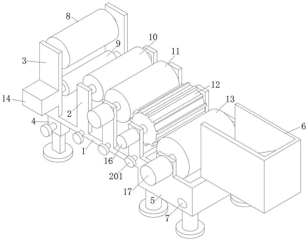
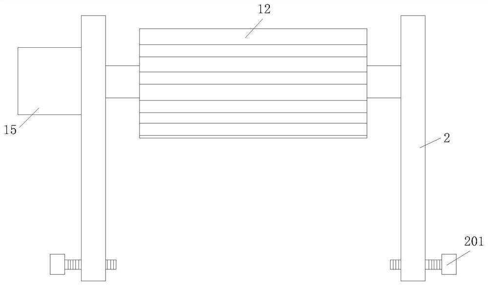
[0023] Such as Figure 1-Figure 4 As shown, a printing machine with a flexographic printing head according to the present invention includes a base plate 1, a support leg 4, and an ink tank 5. The top of the base plate 1 is provided with a plurality of first support plates 2, and one end of the first support plate 2 is A fixed rod 201 is installed, and the first support plate 2 is respectively provided with an impression cylinder 10, an ink transfer roller 11, a printing plate cylinder 12, and an ink fountain roller 13, and one end of the ink transfer roller 11 is connected with a second motor 15, and the printing plate cylinder 12 One end is connected with a third motor 16, one end of the ink fountain roller 13 is connected with a fourth motor 17...


PUM


Abstract

The invention relates to the technical field of printing machines, in particular to a printing machine with a flexographic printing head. The printing machine comprises a base plate, support legs andan ink trough, wherein a plurality of first support plates are arranged at the top of the base plate; a fixing rod is in threaded fit with one side of each first support plate; and an impression cylinder, an ink transfer roller, a plate cylinder and an ink fountain roller are respectively arranged between the first support plates. During use, the fixing rod is in threaded fit with the first support plates and the base plate, so that the first support plates are fixed to the base plate, rapid mounting of the printing machine with the flexographic printing head is completed, the first support plates are separated from the base plate by unscrewing the fixing rods, and rapid dismounting of the printing machine with the flexographic printing head is completed; and the rapid mounting and dismounting function is beneficial to improving the later maintenance efficiency of the printing machine with the flexographic printing head, reducing the maintenance difficulty, reducing the maintenance cost and improving the maintenance effect.

Description

technical field [0001] The invention relates to the technical field of printing machines, in particular to a printing machine with a flexographic printing head. Background technique [0002] The printing plate of the printing machine with a flexographic printing head has a certain degree of flexibility, the graphic part is raised, and the non-graphic part is concave. When printing, the ink feed roller (rubber roller) in the ink tank first transfers the stained ink to the printing plate cylinder (anilox metal roller), and then the excess ink on the surface of the anilox printing plate cylinder is removed by the ink feed roller. Then the ink is evenly and stably applied to the surface of the ink transfer roller by the printing plate cylinder. When the printing material (such as a plastic film) passes between the ink transfer roller and the impression cylinder, the graphic on the printing plate will Transfer to substrates for clear graphics. [0003] However, the existing pri...

Claims


Application Information

Patent Timeline
IPC IPC(8): B41F5/24B41F13/20B41F31/06B41F13/10B41F13/18B41F31/10B41F19/00
CPCB41F5/24B41F13/10B41F13/18B41F13/20B41F19/00B41F31/06B41F31/10
Inventor 冯睿鸣张翔邵振洋
Owner 淮南雪魔数码科技有限公司
Why Eureka
Try Eureka