


Quick Research
Generate reliable direction feasibility study reports for your R&D in just a few steps.

Technical Q&A
Discover and master advanced knowledge NOW. Basics, ideas, possibilities, all at once.

Find Solutions
As an expert in R&D theories, this can generate solutions to your technical problems instantly.

Evaluate Feasibility
Analyze your overall solution with one click, know your potential R&D risks in advance.

Monitor Landscape
Get weekly tech updates, stay abreast of the latest tech innovations and key insights.
Back face grooving device for wood floor machining
A wood floor and back technology, which is applied in the field of back slotting devices for wood floor processing, can solve the problems of board damage, poor efficiency, and low work efficiency, etc.
- Summary
- Abstract
- Description
- Claims
- Application Information
AI Technical Summary
Problems solved by technology
Method used
Image

Examples
Embodiment 1
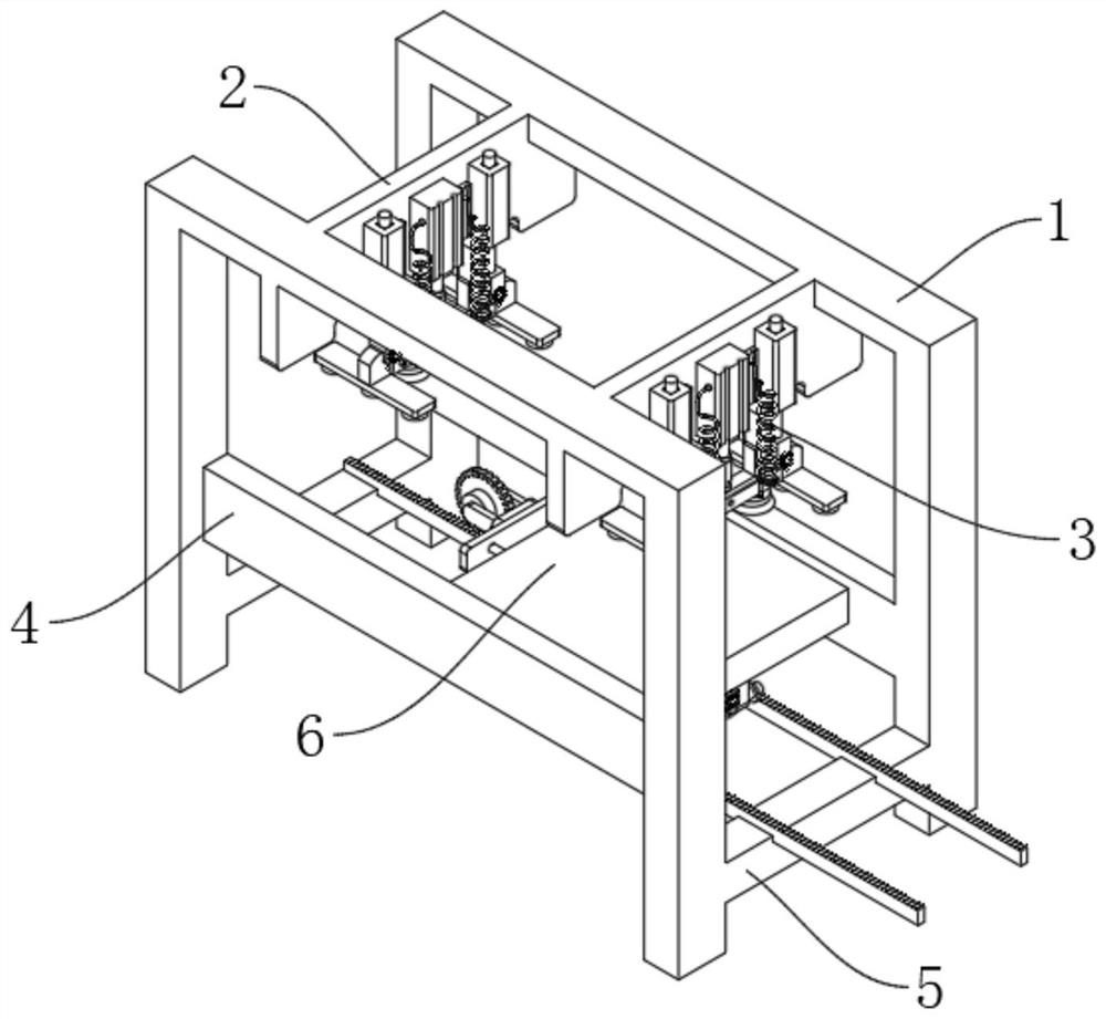
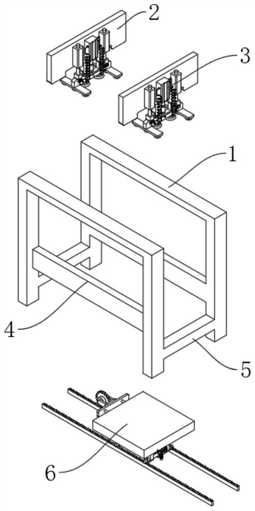
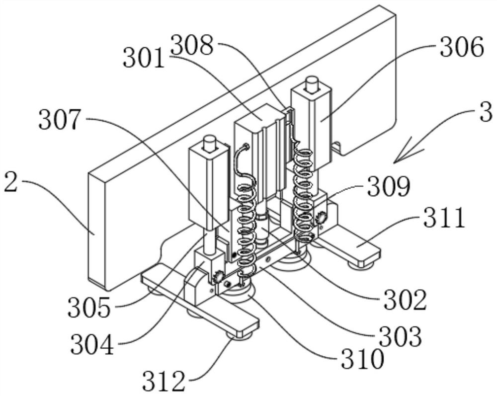
[0029] see Figure 1-3 , a back slotting device for wood floor processing, comprising a support frame 1, a fixed plate 2, a first mounting frame 4 and a second mounting frame 5, the fixed plate 2 is fixedly connected to the upper end of the support frame 1, and the fixed plate 2 The adsorption adjustment device 3 is connected, and the first installation frame 4 and the second installation frame 5 are also fixedly connected with the support frame 1. The first installation frame 4 and the second installation frame 5 are connected with a driving slotting module 6, and the driving slotting module 6 includes a mounting cover 7 and a mounting plate 8, the side wall of the mounting cover 7 is slidably connected to the first mounting bracket 4, the mounting plate 8 is fixedly connected to the bottom end of the mounting cover 7, and the mounting plate 8 is connected with a drive slotting mechanism 9 , the bottom surface of the mounting plate 8 and the second mounting frame 5 are connec...
Embodiment 2
[0034] see Figure 4-5 , the difference in connection with the basis of Embodiment 1 is that the drive slotting mechanism 9 includes a biaxial drive motor 901, the biaxial drive motor 901 is fixedly installed on the bottom surface of the mounting plate 8, and the top output of the biaxial drive motor 901 A first connecting rod 902 is fixedly connected to the shaft, and the end of the first connecting rod 902 away from the biaxial drive motor 901 is rotatably connected to the second connecting rod 903, and the end of the second connecting rod 903 away from the first connecting rod 902 is rotatably connected to the movable block 904 , the movable block 904 is slidably connected to the limiting guide rail 905 , and the limiting guide rail 905 is fixedly connected to the mounting plate 8 .
[0035] The movable block 904 is fixedly connected with a protruding block 906, and the protruding block 906 is fixedly connected with a limit connecting rod 907, and the limit connecting rod 9...
Embodiment 3
[0038] see Image 6 The difference in the basis of Embodiment 1 or 2 is that the travel mechanism 10 includes a first vertical connecting rod 1001 and a worm 1002, the top of the first vertical connecting rod 1001 is fixedly connected to the bottom surface of the mounting plate 8, and the worm 1002 is fixedly connected to the output shaft at the bottom of the dual-axis drive motor 901, the worm 1002 is meshed with the worm wheel 1003, the worm wheel 1003 is fixedly connected to the first linkage shaft 1004, and the first linkage shaft 1004 is rotatably connected to the first vertical link 1001 The bottom end of the first linkage shaft 1004 is fixedly connected with traveling wheels 1005 at both ends, the traveling wheels 1005 match the traveling frame 1006, the traveling frame 1006 is fixedly connected on the second mounting frame 5, and the bottom surface of the mounting plate 8 is also fixed A second vertical connecting rod 1007 is connected, and the bottom end of the second...
PUM
 Abstract
Description
Claims
Application Information
 - R&D Engineer
- R&D Manager
- IP Professional
- Industry Leading Data Capabilities
- Powerful AI technology
- Patent DNA Extraction
Browse by: Latest US Patents, China's latest patents, Technical Efficacy Thesaurus, Application Domain, Technology Topic, Popular Technical Reports.
© 2024 PatSnap. All rights reserved.Legal|Privacy policy|Modern Slavery Act Transparency Statement|Sitemap|About US| Contact US: help@patsnap.com