Welding fixing device
A technology for fixed equipment and welding parts, applied in welding equipment, auxiliary welding equipment, welding/cutting auxiliary equipment, etc., can solve problems such as surface welds are not smooth, fillets are uneven and full, overheating and blackening, etc., and achieve faster Effects of melting speed, weld smoothness, and increased penetration length
- Summary
- Abstract
- Description
- Claims
- Application Information
AI Technical Summary
Problems solved by technology
Method used
Image
Examples
Embodiment 1
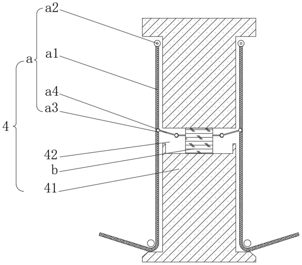
[0039] see Figure 1-2 , the present invention provides a technical solution: a welding and fixing device, including a welding and fixing device body 1 composed of a tray 2, a base 3 and a pole 4, the top of the tray is fixedly connected to the bottom of the base 3, and the top of the base 3 is provided with Groove 31, the bottom of the inner wall of the groove 31 is fixedly connected with the bottom of the pole 4, the outside of the pole 4 is provided with a first weldment 5, the inside of the first weldment 5 is slidingly connected with a second weldment 6, the pole 4 includes a rod body 41, and the inside of the rod body 41 is respectively provided with a fixing mechanism a and a correction mechanism b.
[0040] The fixing mechanism a includes a rotating rod a1. A rotating groove 42 is opened on the outside of the rod body 41. The rotating rod a1 rotates around the inside of the rotating groove 42 through a rotating shaft. The top of the rotating rod a1 is provided with a s...
Embodiment 2
[0043] see Figure 1-5 , on the basis of Embodiment 1, the present invention provides a technical solution: the sliding mechanism a2 includes a sliding bead a21, the middle part of the sliding bead a21 is provided with a rolling hole a22, the top of the rotating rod a1 is fixedly connected with a foot a23, and the rolling hole a22 The inner wall of the rotatably connected with the inside of the leg a23 through the rotating shaft.
[0044] The sliding ball a21 includes a sphere a211, an elastic block a212 is arranged inside the sphere a211, a cavity a213 is opened inside the sphere a211, and a sliding ball a214 is slidably connected to the inside of the cavity a213.
[0045] The rotating rod mechanism a4 includes a rotating rod a41, the top ends of both sides of the rotating rod a41 are fixedly connected with the rotating ball a42, and the left side of the rotating rod a41 extends to the inside of the ball groove a3 through the rotating ball a42 and is rotatably connected with ...
Embodiment 3
[0048] see Figure 1-6 , on the basis of Embodiment 1 and Embodiment 2, the present invention provides a technical solution: the correction mechanism b includes a plate body b1, the outer wall of the plate body b1 is fixedly connected with the inner wall of the rotating groove 42, and the inside of the plate body b1 is provided with a hydraulic pressure The cavity b2, the end of the piston rod a45 away from the groove ball a43 is fixedly connected with the piston b3, the outer wall of the piston b3 is slidingly connected with the inner wall of the hydraulic chamber b2, the right side of the piston b3 is fixedly connected with the magnetic block b4, and the left side of the piston b3 is fixed A spring group b5 is connected, and the end of the spring group b5 away from the piston b3 is fixedly connected with the inside of the plate body b1.
[0049] The bottom of the inner wall of the hydraulic chamber b2 is fixedly connected with a cross partition b6, the inside of the cross pa...
PUM
 Abstract
Description
Claims
Application Information
 - R&D
- Intellectual Property
- Life Sciences
- Materials
- Tech Scout
- Unparalleled Data Quality
- Higher Quality Content
- 60% Fewer Hallucinations
Browse by: Latest US Patents, China's latest patents, Technical Efficacy Thesaurus, Application Domain, Technology Topic, Popular Technical Reports.
© 2025 PatSnap. All rights reserved.Legal|Privacy policy|Modern Slavery Act Transparency Statement|Sitemap|About US| Contact US: help@patsnap.com


