Rotary jitter-type sand and gravel screening device
A screening device, sand and gravel technology, applied in the direction of filtration, solid separation, chemical instruments and methods, etc., can solve the problems of single movement, delay of construction time, single movement track of the screen plate, etc., and achieve synchronous coordination of up and down reciprocating shaking , improve synergistic joint effect, and rationally use the effect of screening space
- Summary
- Abstract
- Description
- Claims
- Application Information
AI Technical Summary
Problems solved by technology
Method used
Image
Examples
Embodiment 1
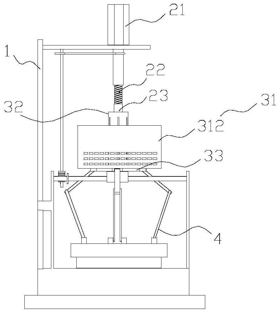
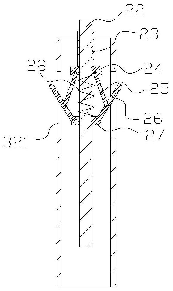
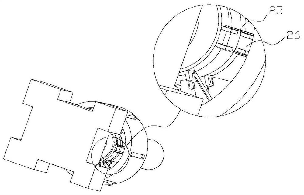
[0049] Such as Figure 1-3 As shown, this embodiment discloses a rotary shaking type sand screening device, including a frame 1, a drive motor 21, a connecting rod 22, a lower pressing member, a movable block 24, a first connecting rod 25, a second connecting rod 26, Fixed sleeve 27, first reset body 28, screen 31, sleeve 32, chassis 33, lifting mechanism. The pressing piece in this embodiment is preferably a screw sleeve 23 .
[0050] The fixed end of the driving motor 21 is fixed on the frame 1, the output shaft of the driving motor 21 is connected with the top of the connecting rod 22, and the bottom of the connecting rod 22 extends downward. The sleeve 32 is sheathed on the periphery of the connecting rod 22 and there is a gap between the sleeve 32 and the connecting rod 22 . The screw sleeve 23, the movable block 24, and the fixed sleeve 27 are limited in the sleeve 32 from top to bottom, wherein the screw sleeve 23 is threadedly matched with the connecting rod 22, the ...
Embodiment 2
[0078] Such as Figure 11 As shown, the difference between this embodiment and the above-mentioned embodiments is that a ring of baffle plates 901 surrounds the outer peripheral side of the mesh structure, and a blanking box 902 with an opening facing upward is arranged under the mesh structure. Sand falling from the gap between the baffle plate 901 and the screen structure and the bottom of the screen structure (ie, the bottom net 311 ) can fall into the blanking box 902 . A sand discharge pipe 903 is communicated with the lower end or bottom of the blanking box body 902 .
[0079] In the present invention, a circle of baffle plate 901 is surrounded on the outer peripheral side of the screen structure, and the material baffle plate 901 can be connected to the frame 1, and a blanking box 902 with an opening facing upward is arranged under the screen structure. After the sand grains are thrown out by the side of the screen structure, under the blocking effect of the material b...
Embodiment 3
[0081] Such as Figure 12-14 As shown, the difference between this embodiment and the above-mentioned embodiments is that the sand outlet pipe 903 is connected with a centralized feeding device, and the centralized feeding device includes a feeding bin 9041, a movable plate 9042, a support spring 9043, a sliding rod 9044, a second reset The elastic body 9045 and the movable plate 9042 slide up and down to be limited in the lower material bin 9041, and its side faces are in sealing contact with the inner wall of the lower material bin 9041. A support spring 9043 is connected between the bottom of the movable plate 9042 and the inner bottom wall of the lower bin 9041 .
[0082] In some embodiments, the support spring 9043 may be a compression spring, and its upper and lower ends may be respectively connected or contacted with the bottom of the movable plate 9042 and the inner bottom wall of the lower bin 9041 .
[0083] On the side of the lower hopper 9041, a discharge port is ...
PUM
 Abstract
Description
Claims
Application Information
 - R&D
- Intellectual Property
- Life Sciences
- Materials
- Tech Scout
- Unparalleled Data Quality
- Higher Quality Content
- 60% Fewer Hallucinations
Browse by: Latest US Patents, China's latest patents, Technical Efficacy Thesaurus, Application Domain, Technology Topic, Popular Technical Reports.
© 2025 PatSnap. All rights reserved.Legal|Privacy policy|Modern Slavery Act Transparency Statement|Sitemap|About US| Contact US: help@patsnap.com


