
A high-efficiency window-breaking hammer for new energy buses

A bus and new energy technology, applied in vehicle components, vehicle safety arrangements, pedestrian/occupant safety arrangements, etc., can solve the problem of difficulty in breaking windows, and achieve the effects of improving safety performance, improving adsorption force, and convenient and labor-saving use.

Active Publication Date: 2021-09-24
浙江恒风集团有限公司公交分公司
View PDF16 Cites 0 Cited by
  • Summary
  • Abstract
  • Description
  • Claims
  • Application Information

AI Technical Summary

Problems solved by technology

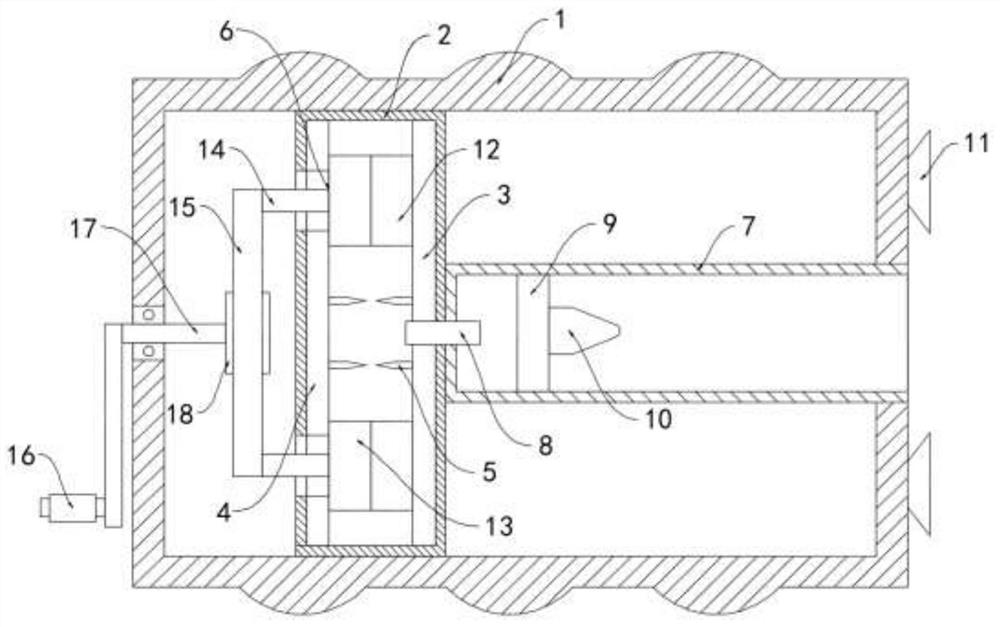
[0005] The purpose of the present invention is to provide a high-efficiency window-breaking hammer for new energy buses with good window-breaking effect in view of the difficulty of breaking windows

Method used


Image

  • A high-efficiency window-breaking hammer for new energy buses
  • A high-efficiency window-breaking hammer for new energy buses
  • A high-efficiency window-breaking hammer for new energy buses

Examples


Embodiment 1

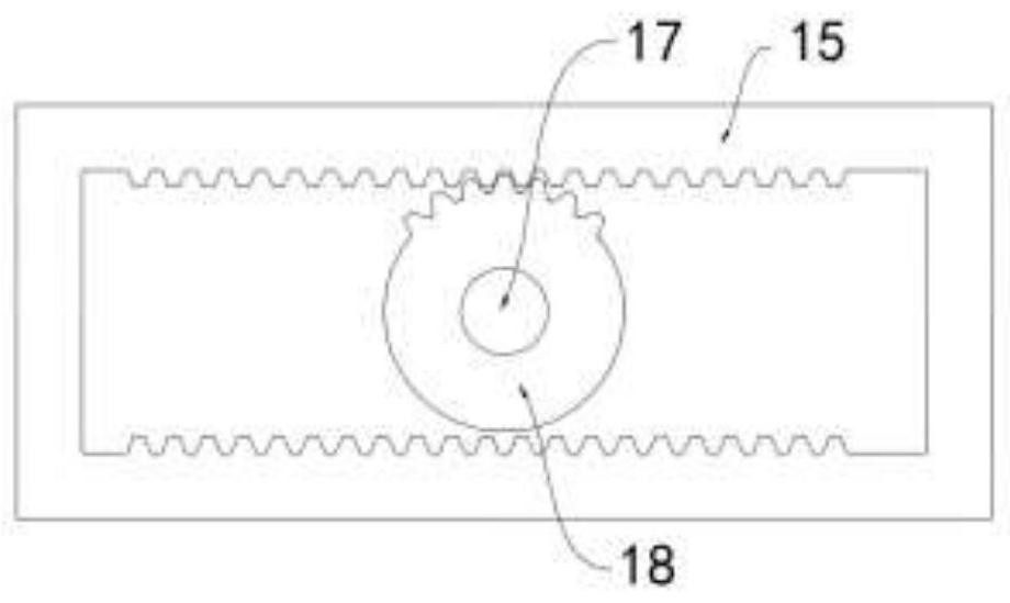
[0020] Such as Figure 1-2 As shown, a high-efficiency window breaking hammer for a new energy bus includes a housing 1, a plurality of suction cups 11 are installed on the side wall of the housing 1, an insulating cylinder 2 is fixedly installed in the housing 1, and the insulating cylinder 2 is filled with There is a mixed gas of methane and air, and the side walls on both sides of the insulating cylinder 2 are respectively fixedly connected with the first induction plate 3 and the second induction plate 4, and the discharge needle 5 is installed on the first induction plate 3 and the second induction plate 4 , a plurality of discharge needles 5 facing each other in pairs and not touching each other, an electrostatic generating mechanism 6 is provided on the insulating cylinder 2, a sliding cylinder 7 is fixedly connected to the side wall of the insulating cylinder 2, and the other end of the sliding cylinder 7 runs through the housing 1 The side wall of the sliding cylinder...

Embodiment 2

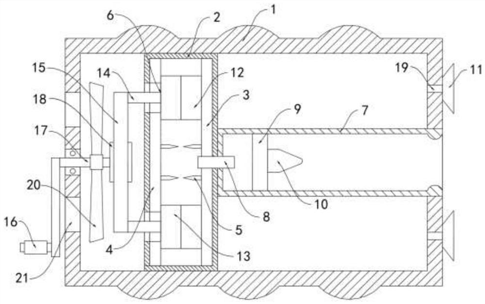
[0024] Such as image 3 As shown, the difference between this embodiment and Embodiment 1 is that the suction cup 11 communicates with the inside of the housing 1 through the one-way communication pipe 19, and the fan 20 is coaxially fixedly sleeved outside the rotating shaft 17, and the housing 1 is close to the fan 20 to blow air. Vent holes 21 are opened on the side wall of the surface.

[0025] In this embodiment, the fan 20 can rotate synchronously with the rotating shaft 17, and discharge the air in the casing 1 through the exhaust hole 21, so that a negative pressure is formed in the casing 1 and the suction cup 11, and the adsorption between the suction cup 11 and the surface of the glass to be broken is improved. to further enhance its safety performance.


PUM


Abstract

The invention belongs to the field of new energy buses, and in particular relates to a high-efficiency window breaking hammer for new energy buses, which includes a housing, an insulating cylinder is fixedly installed in the housing, and the insulating cylinder is filled with a mixed gas of methane and air , the side walls on both sides of the insulating cylinder are respectively fixedly connected with a first induction plate and a second induction plate, and discharge needles are installed on the first induction plate and the second induction plate, and a plurality of discharge needles are two The two are opposite and do not touch each other. The insulating cylinder is provided with a static electricity generating mechanism, and the side wall of the insulating cylinder is fixedly connected with a sliding cylinder. The invention can ignite the methane gas in the insulating cylinder through the principle of frictional electricity generation, and push the hammer head to quickly hit the glass window door to effectively break the glass, which is convenient to use and labor-saving, and the position of the broken window does not need to be limited to the four corners of the glass window door. It can also quickly and effectively break the window in a small and limited space, which greatly improves the possibility of passengers escaping in the event of an accident.

Description

technical field [0001] The invention belongs to the field of new energy buses, in particular to a high-efficiency window breaking hammer for new energy buses. Background technique [0002] With the popularization of new energy vehicles, the fire prevention and disaster prevention facilities in new energy vehicles have also increased accordingly. Among them, the window breaking hammer is an important auxiliary escape tool, which can be easily taken out in emergency situations such as car fire or falling into water. And smashed glass windows and doors to escape smoothly. [0003] When the existing window-breaking hammer is in use, it is often necessary to repeatedly hammer the four corners of the glass window and door to break the tempered glass. However, when an accident occurs and the carriage is distorted and deformed, passengers often It is difficult to accurately hammer the four corners of the glass window and door, which increases the difficulty of breaking the window, ...

Claims


Application Information

Patent Timeline
Patent Type & Authority Patents(China)
IPC IPC(8): B60R21/02A62B3/00
CPCA62B3/005
Inventor 罗桃艳杨秋燕
Owner 浙江恒风集团有限公司公交分公司
Learn More