
Firefighter distress call device

A technology for calling for help and firefighters, applied to instruments, alarms, etc., can solve problems such as large limitations, no recording function, and inability to provide all-round protection for firefighters, and achieve the effect of improving accuracy and efficiency

Pending Publication Date: 2021-02-09
江西鼎峰装备科技有限公司
View PDF0 Cites 0 Cited by
  • Summary
  • Abstract
  • Description
  • Claims
  • Application Information

AI Technical Summary

Problems solved by technology

However, the traditional rescue device has a single function and cannot provide all-round protection for firefighters, and it does not have a recording function. It is not convenient for the later command personnel to absorb the successful experience of the rescue plan in the accident through on-site recording, which has great limitations.

Method used


Image

  • Firefighter distress call device
  • Firefighter distress call device
  • Firefighter distress call device

Examples


Embodiment 1

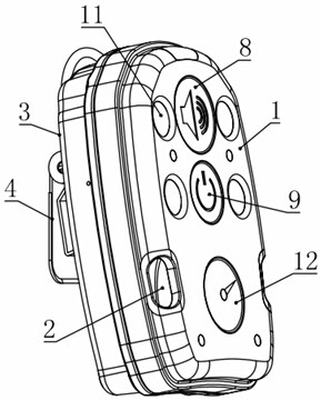
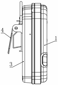
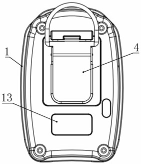
[0025] see Figure 1-4 , in an embodiment of the present invention, a firefighter's call for help includes a housing 1 and a rear cover 3 that are arranged in cooperation. The inner sides of the housing 1 and the rear cover 3 are respectively installed with a battery 6, a buzzer fixing plate 7, A circuit board 5, a GPS positioning module 10, a wireless communication module 14, a recording module (not shown) and a storage module (not shown), and a call switch 8 and a power switch 9 are respectively installed in the middle of the outer upper part of the shell 1, and call for help A plurality of flashlights 11 are also arranged on the periphery of the switch 8 and the power switch 9, a compass 12 is installed in the middle of the outer lower part of the casing 1, and a buzzer 2 is respectively installed on both sides of the compass 12, and the casing 1 and the rear cover 3 form a whole The inner buzzer fixing plate 7 is arranged corresponding to the buzzer 2, and the outer shell ...

Embodiment 2

[0028] see Figure 1-4 , the difference between this embodiment and embodiment 1 is:

[0029] In this embodiment, a duckbill clip 4 is installed on the rear side of the back cover 3, and the duckbill clip 4 facilitates the wearing of the device.

[0030] In this embodiment, the casing 1 and the back cover 3 are fixed by screw fit, and the outside of the casing 1 and the back cover 3 is provided with a high-temperature-resistant waterproof membrane (not shown), and the application of the lifting device is reliable. sex.

[0031] In this embodiment, four flash lamps 11 are arranged in a matrix on the casing 1 to enhance the flash alarm effect of the flash lamps 11 .

[0032] The firefighter's rescue device can be used as personal protective equipment in the process of fire rescue. It transmits strong alarm audio to the outside through the static time of the personnel (more than 30 seconds for the pre-alarm function, if there is no action during the period, the product performs...


PUM


Abstract

The invention relates to the field of fire-fighting tools, in particular to a firefighter distress call device which comprises a shell and a rear cover which are arranged in a matched mode, and a battery, a circuit board, a GPS positioning module, a wireless communication module, a recording module and a storage module are installed on the inner side of a whole formed by the shell and the rear cover. A distress switch and a power switch are respectively installed in the middle of the upper portion of the outer side of the outer shell, a plurality of flash lamps are further arranged on the periphery of the distress switch and the periphery of the power switch, buzzers are further respectively installed on two sides of the lower portion of the outer side of the outer shell, and a microphoneand a microUSB interface are further respectively arranged on the outer shell. The firefighter distress call device is rich in function, can provide comprehensive protection for firefighters, has a recording function, is convenient for command personnel to absorb successful experience of a rescue scheme in an accident through on-site recording in the later period, and is worth popularizing.

Description

technical field [0001] The invention relates to the field of fire-fighting tools, in particular to a firefighter's rescue device. Background technique [0002] Firefighters, members of disaster relief groups established by the government or civil society. The duties of firefighters are mainly to extinguish fires and provide ambulance services, but also participate in other rescue work. [0003] Firefighters generally need to wear a rescue device. The traditional firefighter's rescue device has two functions of azimuth light and rescue device, realizing one machine with two functions. However, the traditional rescue device has a single function, cannot provide all-round protection for firefighters, and does not have a recording function, which is not convenient for the later command personnel to absorb the successful experience of the rescue plan in the accident through on-site recording, and has relatively large limitations. [0004] Therefore, for the above present situat...

Claims


Application Information

Patent Timeline
IPC IPC(8): G08B21/02G08B21/04
CPCG08B21/02G08B21/0263G08B21/0453
Inventor 柳斌柳宏伟
Owner 江西鼎峰装备科技有限公司
Learn More