


Quick Research
Generate reliable direction feasibility study reports for your R&D in just a few steps.

Technical Q&A
Discover and master advanced knowledge NOW. Basics, ideas, possibilities, all at once.

Find Solutions
As an expert in R&D theories, this can generate solutions to your technical problems instantly.

Evaluate Feasibility
Analyze your overall solution with one click, know your potential R&D risks in advance.

Monitor Landscape
Get weekly tech updates, stay abreast of the latest tech innovations and key insights.
Monitoring method, system and device for cracks caused by foundation pit displacement and storage medium
A displacement and foundation pit technology, applied in image analysis, image enhancement, instruments, etc., can solve the problems of manpower consumption, untimely detection of danger, etc., and achieve the effect of easy processing, intuitive comparison results, and simple operation.
- Summary
- Abstract
- Description
- Claims
- Application Information
AI Technical Summary
Problems solved by technology
Method used
Image

Examples
Embodiment 1
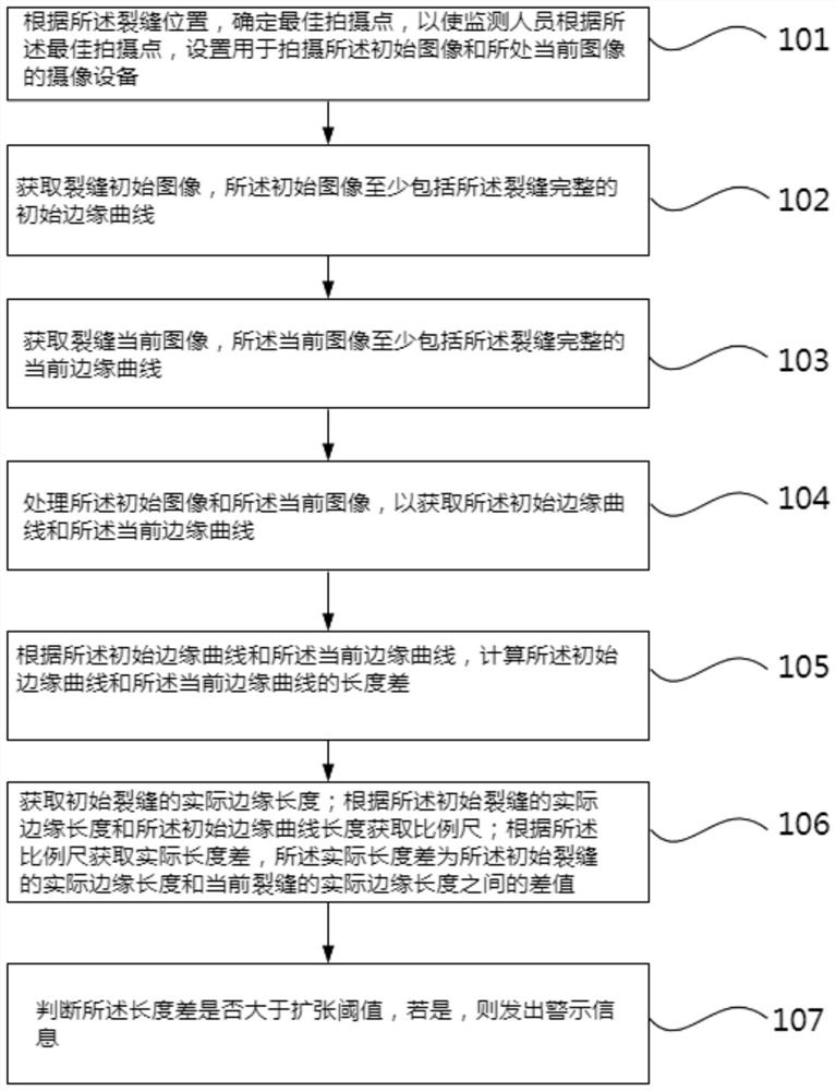
[0071] Crack monitoring method caused by foundation pit displacement, refer to figure 1 ,include:
[0072] 101. Determine the best shooting point according to the crack position, so that the monitoring personnel set up the camera equipment for shooting the initial image and the current image according to the best shooting point.
[0073] Specifically, confirm the plane where the crack is located, start from the midpoint of the crack, extend a ray along the direction perpendicular to the plane where the crack is located, until the ray touches any support, the support can be the ground, other buildings, street lights Wait.
[0074] Use the support as a pre-shooting point, place the camera, and keep the surface of the camera parallel to the plane where the crack is located.
[0075] At the pre-shooting point, the image of the crack is taken by the camera, and it is judged whether the crack is blocked by other sundries, such as leaves, etc. If it is blocked, the pre-shooting poi...
Embodiment 2
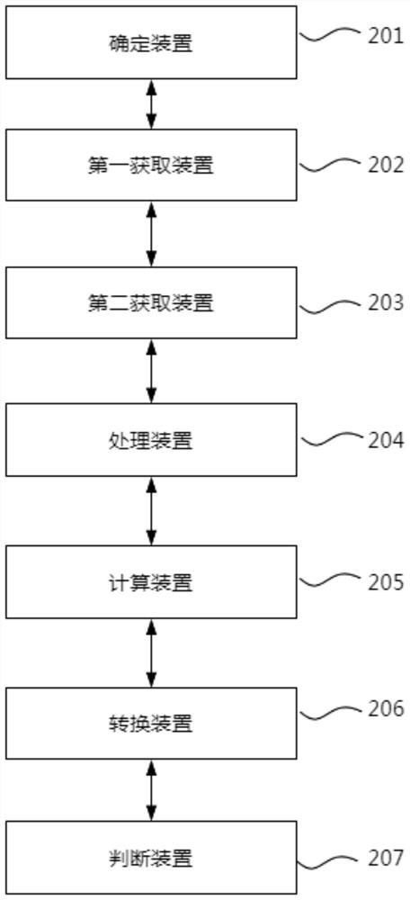
[0141] Crack monitoring system caused by excavation displacement, refer to figure 2 ,include:
[0142] The determining means 201 determines the best shooting point according to the position of the crack, so that the monitoring personnel can set the camera equipment for shooting the initial image and the current image according to the best shooting point.
[0143] The first acquiring means 202 acquires an initial image of the crack, where the initial image at least includes a complete initial edge curve of the crack.
[0144] The second obtaining means 203 is to obtain a current image of the fracture, where the current image at least includes a complete current edge curve of the fracture.
[0145] The processing device 204 is configured to process the initial image and the current image to obtain the initial edge curve and the current edge curve.
[0146] Further, grayscale processing is performed on the initial image and the current image respectively, and the multi-pass co...
Embodiment 3
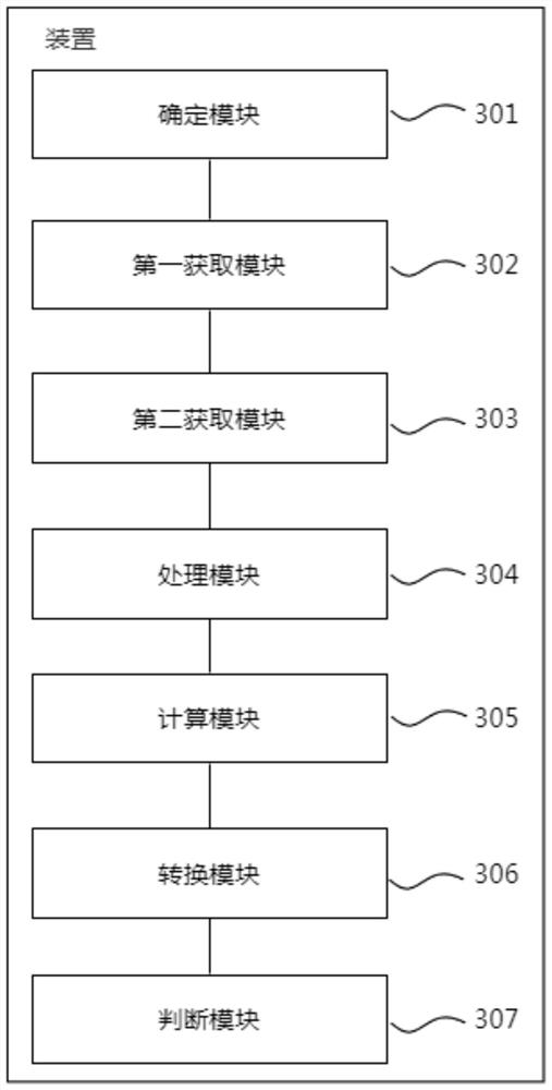
[0160] Crack monitoring device caused by foundation pit displacement, refer to image 3 ,include:
[0161] The determining module 301 determines the best shooting point according to the position of the crack, so that the monitoring personnel can set the camera equipment for shooting the initial image and the current image according to the best shooting point.
[0162] The first acquiring module 302 acquires an initial image of the crack, where the initial image at least includes a complete initial edge curve of the crack.
[0163] The second acquiring module 303 acquires a current image of the fracture, where the current image at least includes a complete current edge curve of the fracture.
[0164]The processing module 304 is configured to process the initial image and the current image to obtain the initial edge curve and the current edge curve.
[0165] Further, grayscale processing is performed on the initial image and the current image respectively, and the multi-pass c...
PUM
 Abstract
Description
Claims
Application Information
 - R&D Engineer
- R&D Manager
- IP Professional
- Industry Leading Data Capabilities
- Powerful AI technology
- Patent DNA Extraction
Browse by: Latest US Patents, China's latest patents, Technical Efficacy Thesaurus, Application Domain, Technology Topic, Popular Technical Reports.
© 2024 PatSnap. All rights reserved.Legal|Privacy policy|Modern Slavery Act Transparency Statement|Sitemap|About US| Contact US: help@patsnap.com