
Rolling bearing fault diagnosis method and system, storage medium, equipment and application

A fault diagnosis system and rolling bearing technology, applied in computational models, testing of mechanical components, artificial life, etc., can solve problems such as large amount of calculation, parameter optimization of least squares support vector machine model, and difficulty in extracting fault features of bearing vibration signals. , to achieve the effect of maintaining diversity, ensuring convergence speed and accuracy, and avoiding premature maturity

Pending Publication Date: 2021-02-09
XIDIAN UNIV
View PDF4 Cites 19 Cited by
  • Summary
  • Abstract
  • Description
  • Claims
  • Application Information

AI Technical Summary

Problems solved by technology

[0006] (1) It is difficult to extract the fault features in the current bearing vibration signal
[0007] (2) The problem of parameter optimization of the least squares support vector machine model in the current bearing fault diagnosis
[0009] (1) The complexity of the background noise: the environment of the general equipment site is very complex. When the machine is working, there are a large number of interference signals around it. Some of these signals are periodic, while others have strong randomness.
Sometimes the acoustic signal emitted by the equipment can even be overwhelmed by the environmental noise, so it is still very difficult to extract the fault signal from the complex environment
[0010] (2) The defect of the least squares support vector machine model is that the computational complexity is about the cubic level of the number of samples, and the amount of calculation is very large

Method used


Image

  • Rolling bearing fault diagnosis method and system, storage medium, equipment and application
  • Rolling bearing fault diagnosis method and system, storage medium, equipment and application
  • Rolling bearing fault diagnosis method and system, storage medium, equipment and application

Examples


Embodiment Construction

[0086] In order to make the object, technical solution and advantages of the present invention more clear, the present invention will be further described in detail below in conjunction with the examples. It should be understood that the specific embodiments described here are only used to explain the present invention, not to limit the present invention.

[0087] Aiming at the problems existing in the prior art, the present invention provides a rolling bearing fault diagnosis method, system, storage medium, equipment and application. The present invention will be described in detail below with reference to the accompanying drawings.

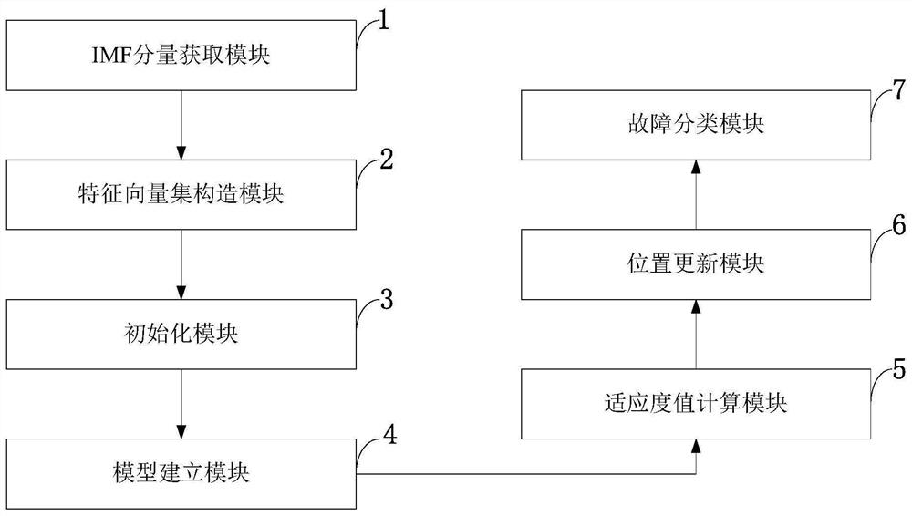
[0088] Such as figure 1 As shown, the rolling bearing fault diagnosis method provided by the present invention includes the following steps:

[0089] S101: Collect the original signals in the four states of the bearing, use VMD to decompose the signals, and obtain each IMF component;

[0090] S102: Using multi-scale permutation entropy to extr...


PUM


Abstract

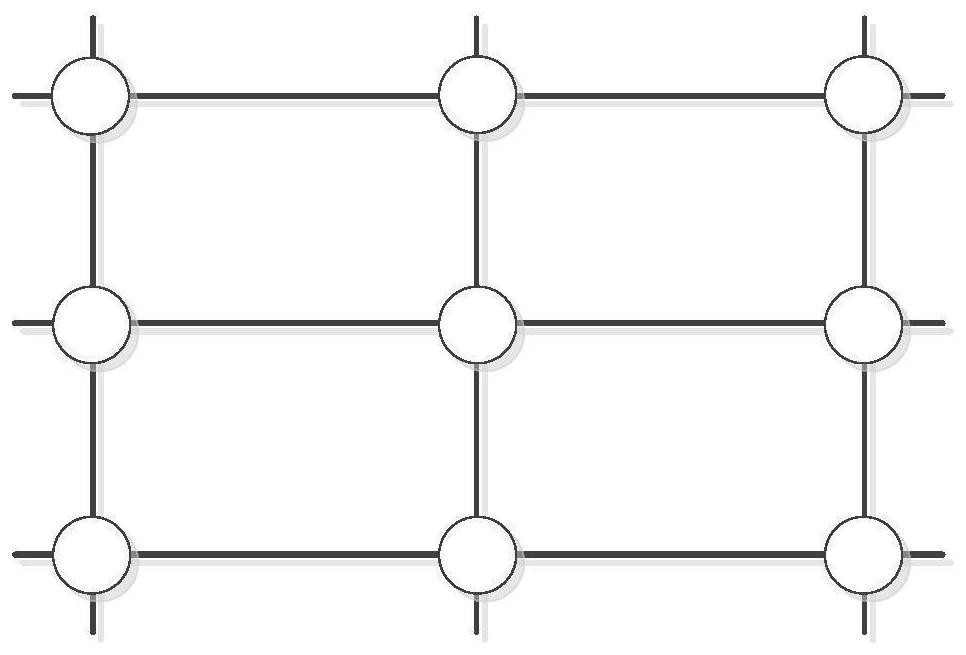
The invention belongs to the technical field of bearing vibration signal identification, and discloses a rolling bearing fault diagnosis method and system, a storage medium, equipment and application,and the method comprises the steps: collecting original signals of a bearing in four states, carrying out the signal decomposition through VMD, and obtaining all IMF components; extracting signal features by using multi-scale permutation entropy, constructing a feature vector set, and dividing the feature vector set into a training sample and a test sample; initializing a whale algorithm population scale, an iteration frequency and an adaptive weight value; establishing an LSSVM model by using the initialization parameters; calculating a fitness value corresponding to each whale, and sortingthe whale according to the fitness; carrying out neighborhood search by adopting a von Noemann topological structure, carrying out information exchange in a neighborhood, finding an optimal whale in the neighborhood, and carrying out position updating according to a formula; and outputting the whale position with the optimal fitness as the parameter of the LSSVM for training, and carrying out fault classification on the test set. The method is better in fault classification performance and higher in accuracy.

Description

technical field [0001] The invention belongs to the technical field of bearing vibration signal identification, and in particular relates to a rolling bearing fault diagnosis method, system, storage medium, equipment and application. Background technique [0002] At present: As an important part of rotating machinery, rolling bearings are also one of the most prone to failure components. Due to the poor working environment, problems such as resonance are prone to occur. Therefore, timely and accurate detection and diagnosis of rolling bearings are of great significance. , the signals of rolling bearings are often highly non-stationary and nonlinear, and the characteristics of these signals are difficult to identify. At present, the commonly used diagnostic method is to collect vibration signals through sensors first, and then use signal processing methods such as Fourier transform and wavelet transform to analyze The vibration signal is processed, its features are extracted,...

Claims


Application Information

Patent Timeline
Patent Type & Authority Applications(China)
IPC IPC(8): G06K9/00G01M13/045G06N3/00
CPCG01M13/045G06N3/006G06F2218/08G06F2218/12
Inventor 齐小刚蔡赛男刘立芳冯海林
Owner XIDIAN UNIV
Learn More