
Rendering method of real-time optical smoke screen based on physical process

A physical process and optical technology, applied in the field of optical smoke screen, can solve the problems of unrealistic simulation results, large smoke gap, simple infrared illumination model, etc.

Active Publication Date: 2021-02-09
XIDIAN UNIV
View PDF3 Cites 3 Cited by
  • Summary
  • Abstract
  • Description
  • Claims
  • Application Information

AI Technical Summary

Problems solved by technology

Later, the researchers applied the fluid dynamics model to the real-time simulation of infrared smoke screens. The fluid dynamics model adopted the Stable Fluid model, and CUDA was used as a development tool to accelerate the fluid simulation, which met the real-time requirements. However, the infrared illumination model was relatively simple. The rendering effect is poor, there is a big gap with the real smoke, and the simulation result is not realistic enough

Method used


Image

  • Rendering method of real-time optical smoke screen based on physical process
  • Rendering method of real-time optical smoke screen based on physical process
  • Rendering method of real-time optical smoke screen based on physical process

Examples


Embodiment 1

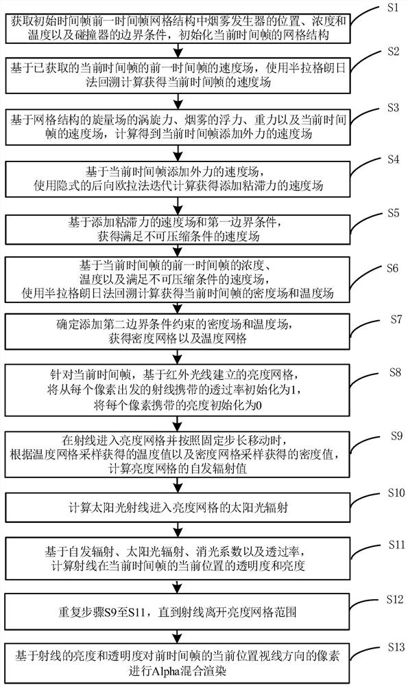
[0027] Such as figure 1 As shown, a physical process-based real-time optical smoke rendering method provided in an embodiment of the present invention includes:

[0028] S1, obtain the position, concentration and temperature of the smoke generator and the boundary conditions of the collider in the grid structure of the previous time frame of the initial time frame, and initialize the grid structure of the current time frame;

[0029] Wherein, the grid structure is a vector face-centered grid with regular Cartesian coordinates, and the 6 face-centered positions of each unit grid in the grid structure store the velocity of the position, the unit grid central position stores the density, the pressure and temperature;

[0030] S2, based on the obtained velocity field of the previous time frame of the current time frame, the velocity field of the current time frame is obtained by backtracking calculation using the semi-Lagrangian method;

[0031] S3, based on the vortex force of ...

Embodiment 2

[0047] As an optional implementation manner of the present invention, before the step of S3, the rendering method further includes:

[0048] S31, calculating the vortex vector for each point of the velocity field of the current time frame;

[0049] S32. Determine a curl gradient vector from the vortex vector;

[0050]S33. Determine the cross product of the vortex vector and the curl gradient vector, the product of the grid size and the vortex coefficient as the vortex force of the spinor field of the grid structure.

Embodiment approach

[0052] As an optional implementation manner of the present invention, the step of S5 includes:

[0053] S51, establishing a pressure iteration matrix based on the velocity field with added viscous force and the first boundary condition;

[0054] S52, using the parallel ultra-relaxed Gauss-Seidel iteration method to iterate the pressure matrix to obtain a pressure field;

[0055] S53. Superimpose the pressure field on the velocity field to obtain a velocity field satisfying an incompressible condition.


PUM


Abstract

According to a real-time optical smoke screen rendering method based on the physical process provided by the embodiment of the invention, in the process of rendering smoke by utilizing an illuminationsmoke model and an infrared smoke model, a density grid, a temperature grid and a brightness grid are obtained through calculation according to the influence of factors such as background radiation,an external light source and the transmittance of the smoke on smoke rendering; meanwhile, a spontaneous radiation model is introduced into the infrared model, the transparency and brightness of smokeare calculated based on a density grid, a temperature grid and a brightness grid meter, and mixed rendering is conducted on pixels in the sight line direction of the current position of a previous time frame based on the brightness and transparency of rays; and the visual authenticity and the illumination accuracy of smoke rendering are improved while the efficiency is considered.

Description

technical field [0001] The invention belongs to the field of optical smoke screens, and in particular relates to a physical process-based rendering method for real-time optical smoke screens. Background technique [0002] Smoke simulation is a subproblem of incompressible low-velocity flow in computational fluid dynamics. This kind of low-velocity fluid exists widely in the real natural environment. In order to improve the rendering realism of the scene, how to efficiently and realistically render this kind of low-velocity fluid has become an unavoidable hot issue in computer graphics. The most common low-velocity fluids in life are smoke and flowing water, both of which are solutions to the incompressible NS equations. The main difference is that the water body has an additional boundary condition of the liquid surface, which causes the smoke to pay more attention to the overall shape, while the flowing water is more Pay attention to the change of the surface, which leads ...

Claims


Application Information

Patent Timeline
IPC IPC(8): G06F30/28G06T15/55
CPCG06F30/28G06T15/55
Inventor 黄曦雷越马向超孙浩吴鑫刘德连张建奇陈心源
Owner XIDIAN UNIV
Learn More