
Automatic loading and unloading device and method for laser cutting machine

A technology of automatic loading and unloading, laser cutting machine, applied in laser welding equipment, metal processing equipment, welding equipment and other directions, can solve the problems of scratches on the surface of raw materials, excessive rail waste, waste clogging, etc., to achieve the effect of saving labor

Active Publication Date: 2022-04-22
熭多利激光科技(江苏)有限公司
View PDF6 Cites 0 Cited by
  • Summary
  • Abstract
  • Description
  • Claims
  • Application Information

AI Technical Summary

Problems solved by technology

[0004] The purpose of the present invention is to provide an automatic loading and unloading device and method for a laser cutting machine to solve the problem that the laser cutting machine on the market proposed in the background technology above needs to be manually carried by the user during the loading process, and the automatic loading and unloading device is maintained. A large amount of waste is blocked in the automatic loading and unloading device, the surface of the raw material is too scratched, and there is too much waste between the tracks when the material is automatically discharged.

Method used


Image

  • Automatic loading and unloading device and method for laser cutting machine
  • Automatic loading and unloading device and method for laser cutting machine
  • Automatic loading and unloading device and method for laser cutting machine

Examples


Embodiment Construction

[0030] The following will clearly and completely describe the technical solutions in the embodiments of the present invention with reference to the accompanying drawings in the embodiments of the present invention. Obviously, the described embodiments are only some, not all, embodiments of the present invention. Based on the embodiments of the present invention, all other embodiments obtained by persons of ordinary skill in the art without making creative efforts belong to the protection scope of the present invention.

[0031] In the description of the present invention, unless otherwise stated, the meaning of "plurality" is two or more; the terms "upper", "lower", "left", "right", "inner", "outer" , "front end", "rear end", "head", "tail", etc. indicate the orientation or positional relationship based on the orientation or positional relationship shown in the drawings, and are only for the convenience of describing the present invention and simplifying the description, rather...


PUM


Abstract

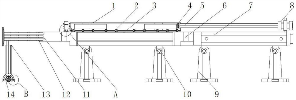
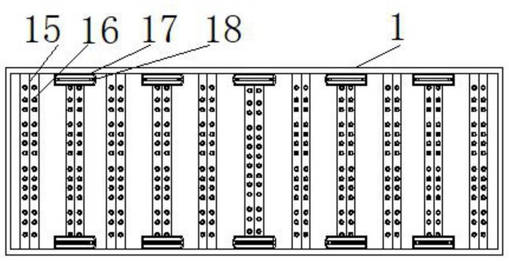
The invention relates to an automatic loading and unloading device and method for a laser cutting machine, comprising an automatic feeding frame, a push plate and a welding bolt, the bottom end of the automatic feeding frame is provided with rollers, and the bottom end of the rollers is provided with a chute frame , one end of the automatic feeding rack is provided with a limit plate, one side of the limit plate is provided with a telescopic rod, and one side of the telescopic rod is provided with an air pressure tube, and the bottom end of the air pressure tube is provided with a lubricating oil rack , and one side of the lubricating oil frame is provided with a waste material passing frame, and the bottom end of the chute frame is provided with a support frame. The beneficial effects of the present invention are: effectively installing the supporting column and the feeding rack between the rails, enabling the supporting column and the feeding rack to slide along the rails, and the supporting column and the feeding rack carrying the cut plate can be Slidingly arranged between the rails, it is convenient for the user to manually push the plate between the support column and the feeding rack, and the cutting plate can be installed between the automatic feeding racks, which can save a lot of labor.

Description

technical field [0001] The invention relates to the technical field of laser cutting machines, in particular to an automatic loading and unloading device and method for a laser cutting machine. Background technique [0002] The laser cutting machine focuses the laser light emitted from the laser device into a high power density laser beam through the optical path system. The laser beam irradiates the surface of the workpiece to make the workpiece reach the melting point or boiling point. At the same time, the high-pressure gas coaxial with the beam will blow away the molten or vaporized metal. It is necessary to improve the structure of the automatic loading and unloading device. [0003] For laser cutting machines on the market, the user needs to manually carry the material during the loading process. When the automatic loading and unloading device is maintained, a large amount of waste is blocked in the automatic loading and unloading device. The surface of the raw materi...

Claims


Application Information

Patent Timeline
Patent Type & Authority Patents(China)
IPC IPC(8): B23K26/70B23K26/16B23K26/38
CPCB23K26/702B23K26/16B23K26/38
Inventor 邓力铭邓钦文
Owner 熭多利激光科技(江苏)有限公司
Learn More