Light guide type lighting decoration device

A light guide and light guide channel technology, which is applied to lighting devices, fixed lighting devices, light guides of lighting devices, etc., can solve the problems of not effectively improving the brightness, waste of light at the opening, and uneven length direction, etc. Display effect, flexible shape design, less waste of light

Pending Publication Date: 2021-02-05
KEBODA TECH CO LTD
View PDF0 Cites 2 Cited by
  • Summary
  • Abstract
  • Description
  • Claims
  • Application Information

AI Technical Summary

Problems solved by technology

However, since each reflective bowl of the bowl-shaped concentrator 4 emits substantially parallel outgoing light, in the length direction, there will be a darker area between the illumination areas of each reflective bowl, that is, along the length direction. A certain inhomogeneity, which is disadvantageous in some cases
Secondly, since the bowl-shaped concentrator 4 needs to be integrally formed, in order to ensure the feasibility of mold processing and facilitate demoulding, the height of the light outlet of the bowl-shaped concentrator 4 cannot be designed too small (generally the height of the light outlet 12 more than 3 times), which will lead to more waste of light at the opening and low light utilization
In addition, the bowl-shaped concentrator 4 mainly utilizes the light emitted by the parabolic reflective area to reflect light from the light source. If the height of the light exit port of the reflective bowl of the bowl-shaped concentrator 4 is reduced, the parabolic reflective area will also become smaller. , the light reflected to the light exit by the parabolic reflective area decreases, and the planar reflective area connected to the parabolic reflective area may face the light source, causing a large amount of light to be reflected to the entrance of the bowl-shaped concentrator 4, thus The brightness at the light outlet of the bowl-shaped concentrator 4 has not been effectively improved

Method used


Image

  • Light guide type lighting decoration device
  • Light guide type lighting decoration device
  • Light guide type lighting decoration device

Examples


Embodiment Construction

[0020] The present invention will be described in detail below in conjunction with the accompanying drawings and specific embodiments.

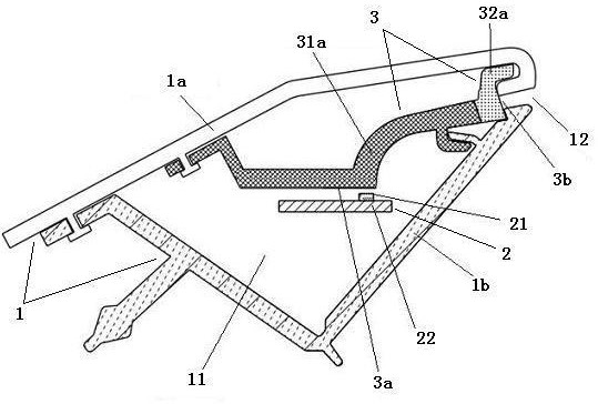
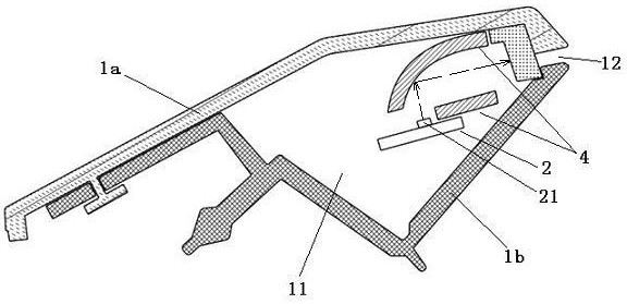
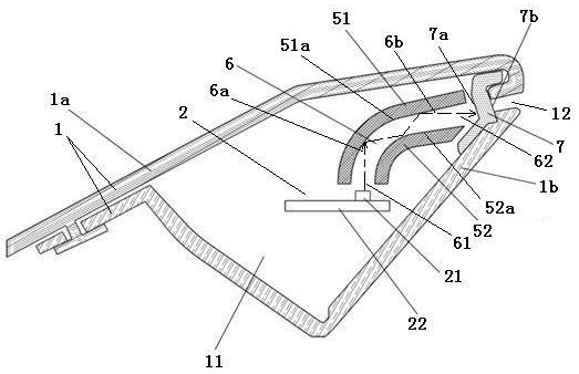
[0021] image 3 A schematic cross-sectional structure diagram of the light-guiding lighting decoration device according to the first embodiment of the present invention is shown. Figure 4 A schematic structural diagram of a light guide cover plate and a light guide bottom plate according to an embodiment of the present invention is shown. see image 3 and Figure 4 . The light guide lighting decoration device according to the first embodiment of the present invention includes a housing 1 , a light source 2 , a non-transparent light guide cover plate 51 and a non-transparent light guide bottom plate 52 .

[0022] The housing 1 has an inner cavity 11 and a light outlet 12 . In this embodiment, the housing 1 is composed of a first housing part 1 a and a second housing part 1 b, and the first housing part 1 a and the second housing part 1 b...


PUM


Abstract

The invention discloses a light guide type lighting decoration device which comprises a shell, a light source and a light guide channel. The shell is provided with an inner cavity and a light outlet,and the light source and the light guide channel are arranged in the inner cavity. The light guide channel is composed of a gap between the light guide cover plate and the light guide bottom plate, and a light guide medium of the light guide channel is air; the light guide channel is provided with a light inlet and a light outlet, and the light inlet and the light outlet are respectively close tothe light source and the light outlet; light emitted by the light source enters the light guide channel through the light incident port, is reflected by the inner side surface of the light guide coverplate and the inner side surface of the light guide bottom plate and then is transmitted to the light outlet. The device has the advantages of low manufacturing cost and high light utilization efficiency, and can fully mix the polychromatic light emitted by the light source.

Description

technical field [0001] The invention relates to lighting decoration technology. Background technique [0002] Common components for vehicle interior lighting and decoration, such as ambient lighting, usually include a light source for emitting light and a strip-shaped light-guiding element. Such as figure 1 As shown, the existing lighting decoration device as an example includes a housing 1 , a light source 2 and a light guide element 3 . The housing 1 has an inner cavity 11 and a light outlet 12. The light source 2 and the light guide element 3 are respectively arranged in the inner cavity 11. The light guide element 3 has a light incident surface 3a for receiving the light incident from the light source 2 and a light incident surface 3a for receiving the incident light. The light is emitted to the light exit surface 3 b of the light exit port 12 . Wherein, the housing 1 is composed of a first housing part 1 a and a second housing part 1 b, and the first housing part 1 a...

Claims


Application Information

Patent Timeline
Patent Type & Authority Applications(China)
IPC IPC(8): F21S8/00F21V15/01F21V8/00F21V7/28F21V17/10F21V5/00F21V19/00B60Q3/62B60Q3/70F21W106/00F21Y115/10
CPCF21S8/00F21V15/01F21V7/28F21V17/10F21V5/002F21V19/001B60Q3/62B60Q3/70F21V2200/00F21W2106/00F21Y2115/10B60Q3/78
Inventor 胡安兴
Owner KEBODA TECH CO LTD
Why Eureka
Try Eureka