Building pile
The invention relates to a technology of building piles and pile heads, which is applied to building piles. It can solve the problems of lack of lateral restraint ability and poor lateral position stability and support of piles.
- Summary
- Abstract
- Description
- Claims
- Application Information
AI Technical Summary
Problems solved by technology
Method used
Image
Examples
Embodiment 1
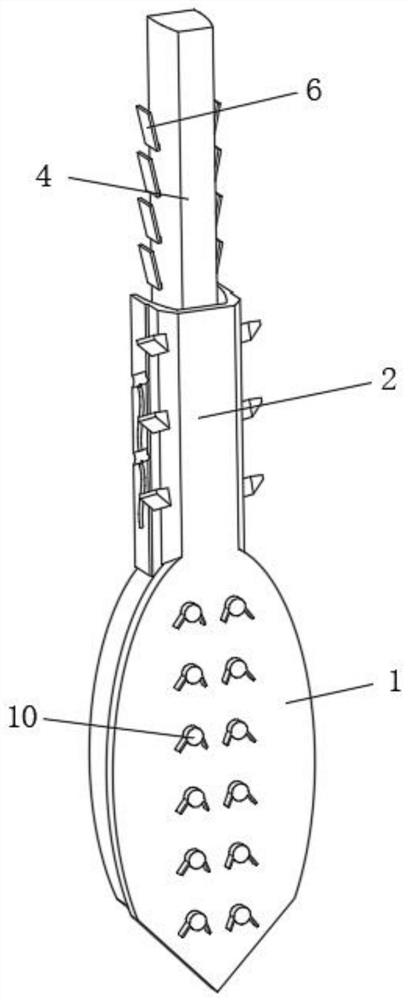
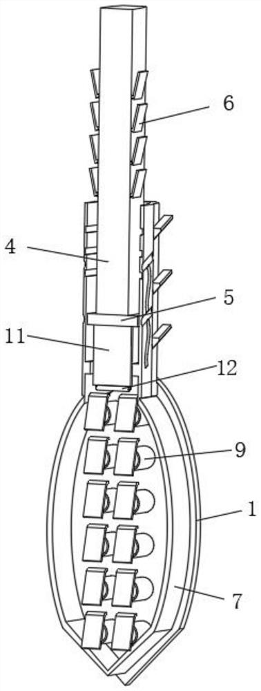
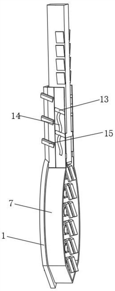
[0039] Such as Figure 1-4 As shown, the present invention provides a technical solution: a construction pile, comprising an outer impact pile head 1, the top of the outer impact pile head 1 is fixedly connected with an outer pile main rod 2, and the inside of the outer pile main rod 2 is provided with a sealing booster. The pressure groove 3 and the vertical position inside the outer pile main rod 2 are penetrated with a ramming ejector 4, and one end of the ramming ejector 4 located inside the sealed pressurized groove 3 is fixedly connected with a sealing backing plate 5, and the outer side of the sealing backing plate 5 It is in contact with and slides inside the sealed pressurized groove 3, and the two sides of the outer surface of the outer pile main rod 2 are evenly rotated and connected with a walking restriction plate 6. The middle position of the outer side of the outer impact pile head 1 is provided with a The mud chute 7, the middle position on both sides of the ou...
Embodiment 2
[0045] Such as Figure 5 As shown, on the basis of Embodiment 1, the present invention provides a technical solution: a construction pile, the explosion driving mechanism 9 includes an impact slide bar 91, and the right side of the impact slide bar 91 is fixedly connected to the outer impact pile head 1, The impact sliding bar 91 is slidingly connected with an impact outer stop bar 92 , and one end of the impact outer stop bar 92 located outside the impact slide bar 91 is fixedly connected with an external contact buffer plate 93 . The impact slide bar 91 and the impact outer stop bar 92 are in a sealed state, and the air pressure is fully converted into dynamic potential energy to ensure the driving force of the lateral limit of the pile.
[0046] The outer contact buffer plate 93 adopts an inclined upward structure, and the surface of the outer contact buffer plate 93 is rollingly connected with the squeeze roller 12 . The pressure roller 12 squeezes and rolls on the surfac...
Embodiment 3
[0050] Such as Figure 6-7 As shown, on the basis of Embodiment 1 and Embodiment 2, the present invention provides a technical solution: a construction pile, the sealing and limiting mechanism 10 includes an impact retaining cover 101, and the inner and outer impact pile heads of the impact retaining cover 101 1 is fixedly connected, and the inside of the impact shield 101 communicates with the impact slide rod 91.
[0051] Both sides of the outer bottom of the shock shield 101 are symmetrically fixedly connected with increasing barriers 102 , inside the shock shield 101 and near the bottom are provided with auxiliary scoring grooves 103 , and the right end of the shock cone 95 is provided correspondingly to the interior of the shock shield 101 . The connection strength at the auxiliary scoring groove 103 is small, and when the explosion driving mechanism 9 impacts the sealing limiting mechanism 10, the directional flip of the sealing limiting mechanism 10 is realized, ensuri...
PUM
 Abstract
Description
Claims
Application Information
 - R&D
- Intellectual Property
- Life Sciences
- Materials
- Tech Scout
- Unparalleled Data Quality
- Higher Quality Content
- 60% Fewer Hallucinations
Browse by: Latest US Patents, China's latest patents, Technical Efficacy Thesaurus, Application Domain, Technology Topic, Popular Technical Reports.
© 2025 PatSnap. All rights reserved.Legal|Privacy policy|Modern Slavery Act Transparency Statement|Sitemap|About US| Contact US: help@patsnap.com


