


Quick Research
Generate reliable direction feasibility study reports for your R&D in just a few steps.

Technical Q&A
Discover and master advanced knowledge NOW. Basics, ideas, possibilities, all at once.

Find Solutions
As an expert in R&D theories, this can generate solutions to your technical problems instantly.

Evaluate Feasibility
Analyze your overall solution with one click, know your potential R&D risks in advance.

Monitor Landscape
Get weekly tech updates, stay abreast of the latest tech innovations and key insights.
Accurate quantitative cutting conveyor belt machining equipment
A processing equipment and conveyor belt technology, applied in metal processing, etc., can solve the problems of increased workload, unfavorable later use, and easy error in the cutting length of the conveyor belt, etc., to achieve the effect of ensuring cutting effect, reducing workload and high cutting efficiency
- Summary
- Abstract
- Description
- Claims
- Application Information
AI Technical Summary
Problems solved by technology
Method used
Image

Examples
Embodiment 1
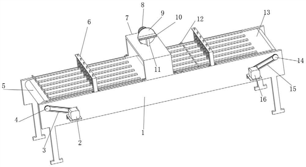
[0035] Such as figure 1 , 2, 3 and 4 shows a conveyor belt processing equipment quantitative cutting precision, including a support frame 1, a first drive motor 2, a first conveyor belt 5, a second conveyor belt 13, a second drive motor 16 and a cutter 17, a support frame The front side wall of 1 is fixedly connected with a first drive motor 2 and a second drive motor 16 through a fixedly connected mounting plate, the output end of the first drive motor 2 is fixedly connected with a third pulley 20, and the third pulley 20 is movably connected with The first belt 3, the first belt 3 is movably connected with a first pulley 4, the inner end of the first pulley 4 is fixedly connected with the rotating roller of the first conveyor belt 5, and the output end of the second drive motor 16 is fixedly connected with a fourth pulley 21 , the fourth pulley 21 is movably connected with the second belt 15, the second belt 15 is movably connected with the second pulley 14, the inner end o...
Embodiment 2
[0037] Embodiment 2 is a further improvement to Embodiment 1.
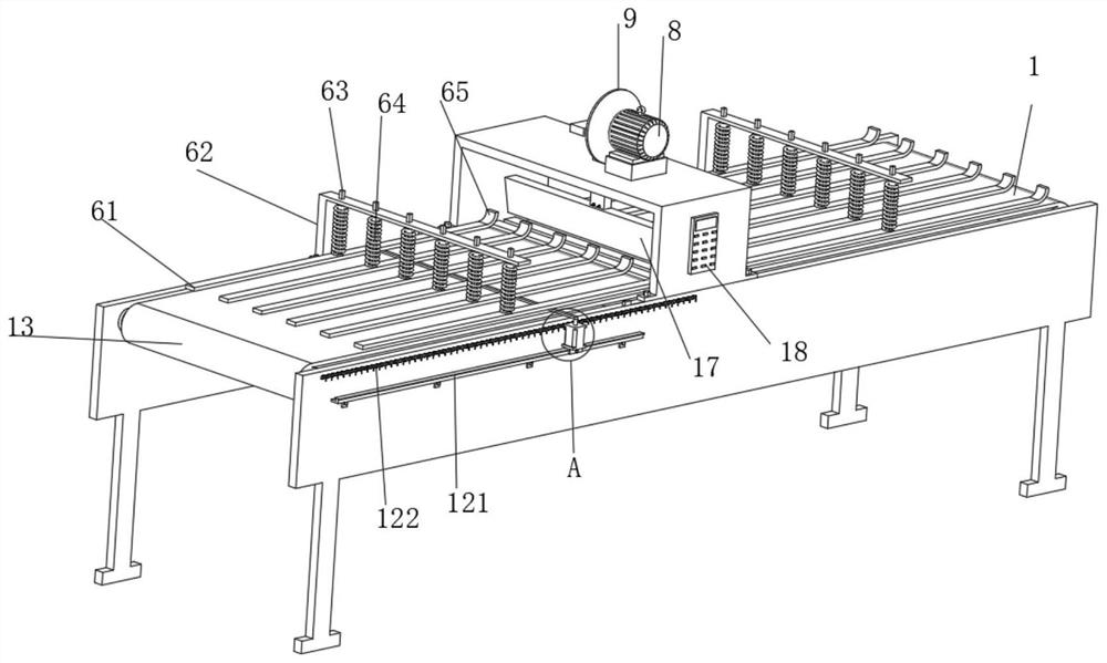
[0038] Such as figure 2 , 3 , a conveyor belt processing equipment for quantitative cutting and precision shown in 6, including a support frame 1, a first drive motor 2, a first conveyor belt 5, a second conveyor belt 13, a second drive motor 16 and a cutter 17, the support frame 1 The front side wall is fixedly connected with a first driving motor 2 and a second driving motor 16 through a fixedly connected mounting plate, the output end of the first driving motor 2 is fixedly connected with a third pulley 20, and the third pulley 20 is movably connected with a first Belt 3, the first belt 3 is movably connected with a first pulley 4, the inner end of the first pulley 4 is fixedly connected with the rotating roller of the first conveyor belt 5, and the output end of the second drive motor 16 is fixedly connected with a fourth pulley 21, Four belt pulleys 21 are movably connected with a second belt 15, and the s...
Embodiment 3
[0040] Embodiment 3 is a further improvement to Embodiment 1.
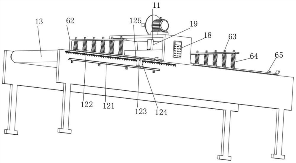
[0041] Such as figure 1 , 2 , 4, 7 shows a quantitative cutting precision conveyor belt processing equipment, including a support frame 1, a first drive motor 2, a first conveyor belt 5, a second conveyor belt 13, a second drive motor 16 and a cutter 17, a support frame The front side wall of 1 is fixedly connected with a first drive motor 2 and a second drive motor 16 through a fixedly connected mounting plate, the output end of the first drive motor 2 is fixedly connected with a third pulley 20, and the third pulley 20 is movably connected with The first belt 3, the first belt 3 is movably connected with a first pulley 4, the inner end of the first pulley 4 is fixedly connected with the rotating roller of the first conveyor belt 5, and the output end of the second drive motor 16 is fixedly connected with a fourth pulley 21 , the fourth pulley 21 is movably connected with the second belt 15, the second belt 15 ...
PUM
 Abstract
Description
Claims
Application Information
 - R&D Engineer
- R&D Manager
- IP Professional
- Industry Leading Data Capabilities
- Powerful AI technology
- Patent DNA Extraction
Browse by: Latest US Patents, China's latest patents, Technical Efficacy Thesaurus, Application Domain, Technology Topic, Popular Technical Reports.
© 2024 PatSnap. All rights reserved.Legal|Privacy policy|Modern Slavery Act Transparency Statement|Sitemap|About US| Contact US: help@patsnap.com