
Epiphyseal plate bone bridge removing device

A removal device and front-end technology, which are applied in bone drill guidance, medical science, surgery, etc., can solve the problems of difficult to accurately determine the position of the bone bridge, cumbersome navigation technology steps, insufficient bone bridge resection range, etc. Rehabilitation, reduction of normal epiphyseal damage by mistake, reduction of operative time and cost

Pending Publication Date: 2021-02-05
THE FIRST AFFILIATED HOSPITAL OF GUANGXI MEDICAL UNIV
View PDF0 Cites 3 Cited by
  • Summary
  • Abstract
  • Description
  • Claims
  • Application Information

AI Technical Summary

Problems solved by technology

Due to the high requirements for fluoroscopy, it is inevitable that there will be problems such as difficult positioning, insufficient bone bridge resection, excessive resection, and the need for a large number of X-ray irradiation for both the operator and the child.
When the bone bridge of the epiphyseal plate is central or the position is scattered irregularly, it is difficult to accurately judge the position of the bone bridge by two-dimensional images, and the line of sight is blocked, and the epiphyseal plate cannot be seen directly, which may easily lead to incomplete grinding or accidental damage to the normal epiphysis plate
Intraoperative 3D CT navigation technology can be applied in the field of pediatric orthopedics to resection of the epiphyseal plate bone bridge, with accurate in vitro positioning, but the steps of navigation technology are cumbersome, the operation time is long, the economic cost is high, the operator has high requirements, and it takes a period of time to learn curve to master

Method used


Image

  • Epiphyseal plate bone bridge removing device
  • Epiphyseal plate bone bridge removing device
  • Epiphyseal plate bone bridge removing device

Examples


Embodiment Construction

[0018] The present invention is described in detail below in conjunction with the accompanying drawings:

[0019] In the description of the present invention, it should be noted that the orientation or positional relationship indicated by "left", "right", "front", "rear", etc. is based on the orientation or positional relationship shown in the drawings, or the invention The orientation or positional relationship that is usually placed when the product is used is only for the convenience of describing the present invention and simplifying the description, rather than indicating or implying that the device or element referred to must have a specific orientation, be constructed and operated in a specific orientation, and therefore cannot be used. It is understood as a limitation of the present invention.

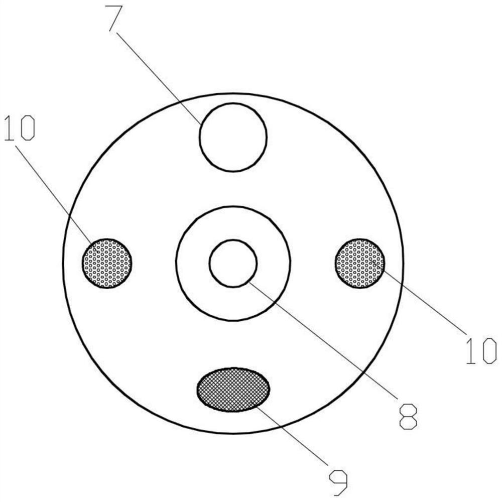
[0020] like figure 1 As shown in the figure, an epiphyseal plate bone bridge removal device includes an operation part 1, an insertion part 2, a bending part 3, a front end pa...


PUM

PropertyMeasurementUnit
Diameteraaaaaaaaaa

Abstract

The invention discloses an epiphyseal plate bone bridge removing device. The device comprises an operation part, an insertion part, a bent part, a front end part, a light guide hose, a light guide plug rod part, a drill bit, a lens, a light hole, a universal flexible shaft, an angle steel wire, a light guide bundle, an image guide bundle, an angle knob and an electric hand drill, wherein the frontend of the operation part is sequentially connected with the insertion part, the bent part and the front end part; the drill bit, the lens and the light hole are arranged on / in the end face of the front end part; the light guide hose and the angle knob are arranged on the side surface of the operation part; the detachable electric hand drill is arranged at the rear end of the operation part; andthe universal flexible shaft, the angle steel wire, the light guide bundle and the image guide bundle are arranged in the insertion part. The design principle of the epiphyseal plate bone bridge removing device is similar to that of a gastrointestinal endoscope, namely an instrument is carried by the insertion part to enter the body to operate a focus part, integrated combination of direct visionand surgical operation is achieved, and the angle of the lens and the angle of the drill bit can be flexibly adjusted during operation, so that the epiphyseal plate bone bridge is effectively and accurately removed.

Description

technical field [0001] The invention belongs to the technical field of medical orthopedic tools, in particular to an epiphyseal plate bone bridge removal device. Background technique [0002] The epiphyseal plate is the active cartilage area between the epiphysis and the metaphysis of children. It has the function of vertical and horizontal growth. Fractures, infections, tumors, and radiation can cause damage to the epiphyseal plate. After the epiphyseal plate is injured, a bony connection, that is, a bone bridge, may be formed in the cartilage area between the epiphysis and the metaphysis, so that all or part of the epiphyseal plate is closed in advance, resulting in limb shortening and / or angular deformity. To prevent later deformity or reduce existing deformity progression, epiphyseal bone bridge resection is an alternative and effective method. The surgical resection methods for the formation of bone bridges after epiphyseal plate injury in children are mainly open surg...

Claims


Application Information

Patent Timeline
IPC IPC(8): A61B17/16A61B17/17A61B90/00
CPCA61B17/16A61B17/1615A61B17/1631A61B17/1703A61B2017/1602A61B90/361
Inventor 丁晓飞廖世杰刘正堂陆荣斌李波香林成森黄乾刘云吴洋陈县祥王天天
Owner THE FIRST AFFILIATED HOSPITAL OF GUANGXI MEDICAL UNIV
Learn More