Green-peel walnut peeling equipment
A technology of walnut peeling and equipment, which is applied in the field of equipment for peeling green walnuts, can solve the problems of walnut peeling time-consuming, laborious work efficiency, and low efficiency, and achieve the effect of facilitating work and improving work efficiency
- Summary
- Abstract
- Description
- Claims
- Application Information
AI Technical Summary
Problems solved by technology
Method used
Image
Examples
Embodiment 1
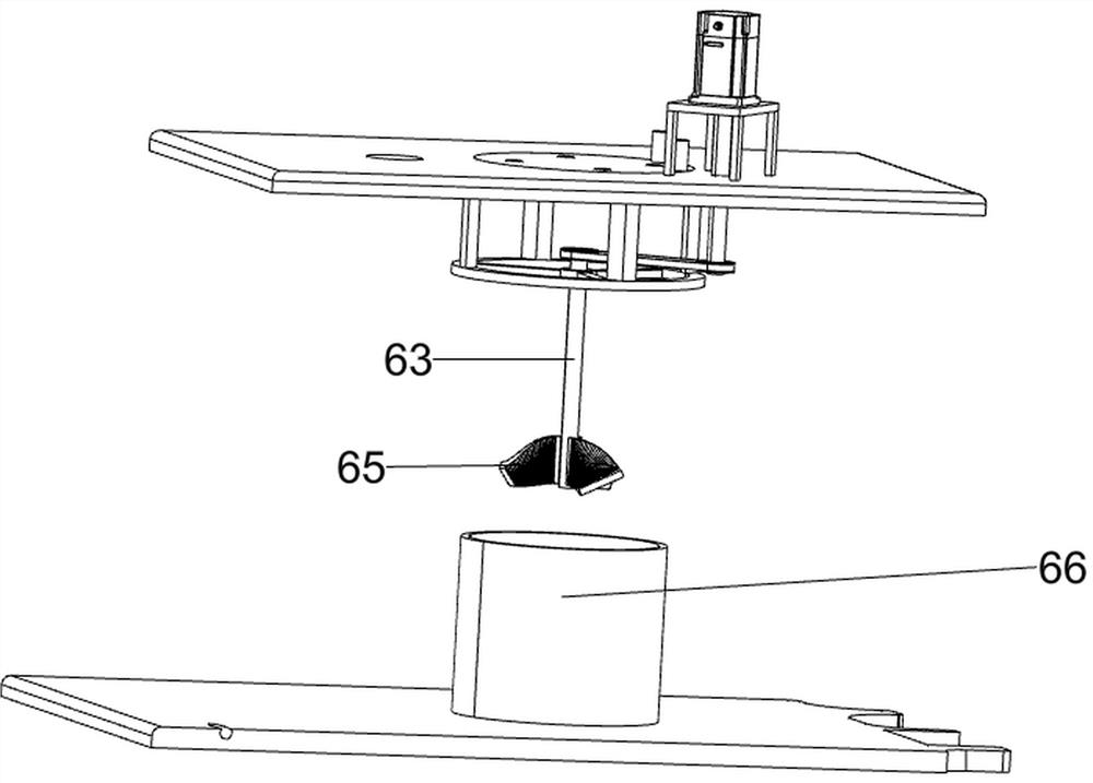
[0079] A kind of green skin walnut peeling equipment, such as figure 1 As shown, it includes a base 1, a first bracket 2, a motor bracket 3, a servo motor 4, a peeling mechanism 5 and a stirring mechanism 6, the top of the base 1 is provided with a first bracket 2, and the top front right of the first bracket 2 is provided with There is a motor support 3, the top of the motor support 3 is provided with a servo motor 4, a peeling mechanism 5 is provided between the right side of the top of the first support 2 and the output shaft of the servo motor 4, and a peeling mechanism 5 is provided between the top of the base 1 and the output shaft of the servo motor 4. Stirring mechanism 6 is arranged.
[0080] When people need to peel the green-skinned walnuts, first put all the green-skinned walnuts into a certain part of the stirring mechanism 6, then start the servo motor 4, and the output shaft of the servo motor 4 drives the peeling mechanism 5 and the stirring mechanism 6 to run,...
Embodiment 2
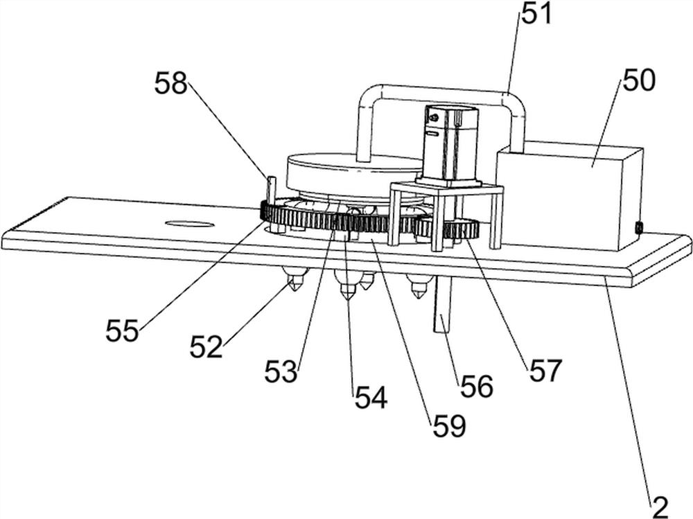
[0082] On the basis of Example 1, such as figure 2 , image 3 , Figure 4 , Figure 5 with Image 6 As shown, the peeling mechanism 5 includes a water pump 50, a water delivery pipe 51, a high pressure nozzle 52, a rotary joint 53, a first support block 54, a gear ring 55, a first rotating rod 56, a spur gear 57, a push block 58 and a first Bearing 59, a water pump 50 is provided at the right rear part of the top of the first support 2, and a water delivery pipe 51 is provided at the left side of the top front side of the water pump 50. High-pressure spray nozzle 52, the first bearing 59 is arranged in the middle of the top of the first support 2, and the bottom of the high-pressure nozzle 52 passes through the top of the first bearing 59. The top of the first bearing 59 is evenly provided with a first support block 54, and the first support block 54 tops are provided with gear ring 55, and servomotor 4 output shafts are provided with first turning bar 56, and the bottom ...
Embodiment 3
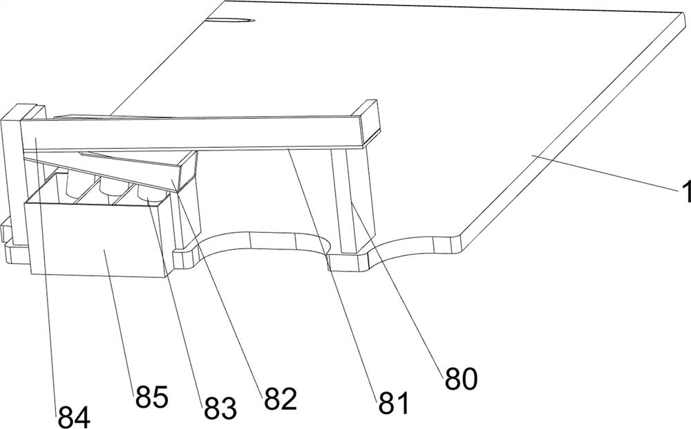
[0089] On the basis of Example 2, such as Figure 7 , Figure 8 , Figure 9 with Figure 10 As shown, it also includes a receiving mechanism 8, and the receiving mechanism 8 includes a support plate 80, a discharge inclined plate 81, a perforated inclined plate 82, a discharge pipe 83, a second baffle plate 84 and a collection box 85, and the base 1 The right side of the top is symmetrically provided with a support plate 80 front and rear, a discharge ramp 81 is arranged between the top of the support plate 80, a second baffle plate 84 is provided on three sides of the top of the discharge ramp 81, and the front side of the bottom of the discharge ramp 81 There is a sloping plate with holes 82, the bottom of the sloping plate with holes 82 is evenly provided with a discharge pipe 83, the front part of the right side of the top of the base 1 is provided with a collection box 85, the collection box 85 is located directly below the discharge pipe 83, and the top of the collecti...
PUM
 Abstract
Description
Claims
Application Information
 - R&D
- Intellectual Property
- Life Sciences
- Materials
- Tech Scout
- Unparalleled Data Quality
- Higher Quality Content
- 60% Fewer Hallucinations
Browse by: Latest US Patents, China's latest patents, Technical Efficacy Thesaurus, Application Domain, Technology Topic, Popular Technical Reports.
© 2025 PatSnap. All rights reserved.Legal|Privacy policy|Modern Slavery Act Transparency Statement|Sitemap|About US| Contact US: help@patsnap.com


