Power conversion device

A power conversion device and current sensor technology, which is applied to output power conversion devices, electrical components, and irreversible DC power input into AC power output and other directions, can solve problems such as changes in detection characteristics of current sensors, and prevent shape deformation. Effect

Pending Publication Date: 2021-02-02
HITACHI ASTEMO LTD
View PDF2 Cites 1 Cited by
  • Summary
  • Abstract
  • Description
  • Claims
  • Application Information

AI Technical Summary

Problems solved by technology

Therefore, there is a possibility that the detection characteristics of the current sensor may change unexpectedly

Method used


Image

  • Power conversion device
  • Power conversion device
  • Power conversion device

Examples


Embodiment Construction

[0024] Hereinafter, an embodiment of the power conversion device of the present invention will be described with reference to the drawings.

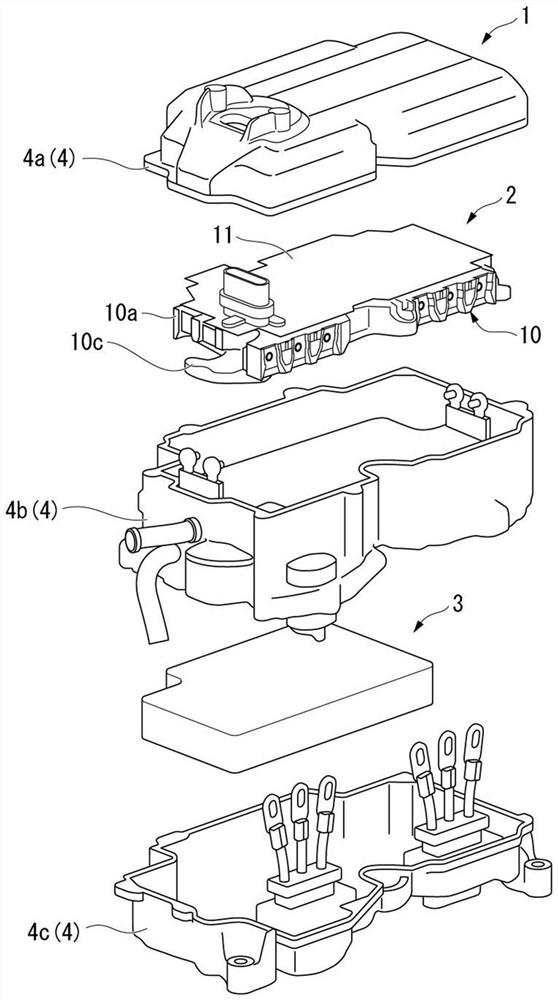
[0025] figure 1 It is an exploded perspective view showing a schematic configuration of the power conversion device 1 of the present embodiment. The power conversion device 1 of the present embodiment is mounted on a vehicle such as an electric automobile, and is installed between a not-shown motor (load) and a storage battery. Such as figure 1 As shown, such a power conversion device 1 according to the present embodiment includes a smart power module 2 , a capacitor 3 , and a main body case 4 .

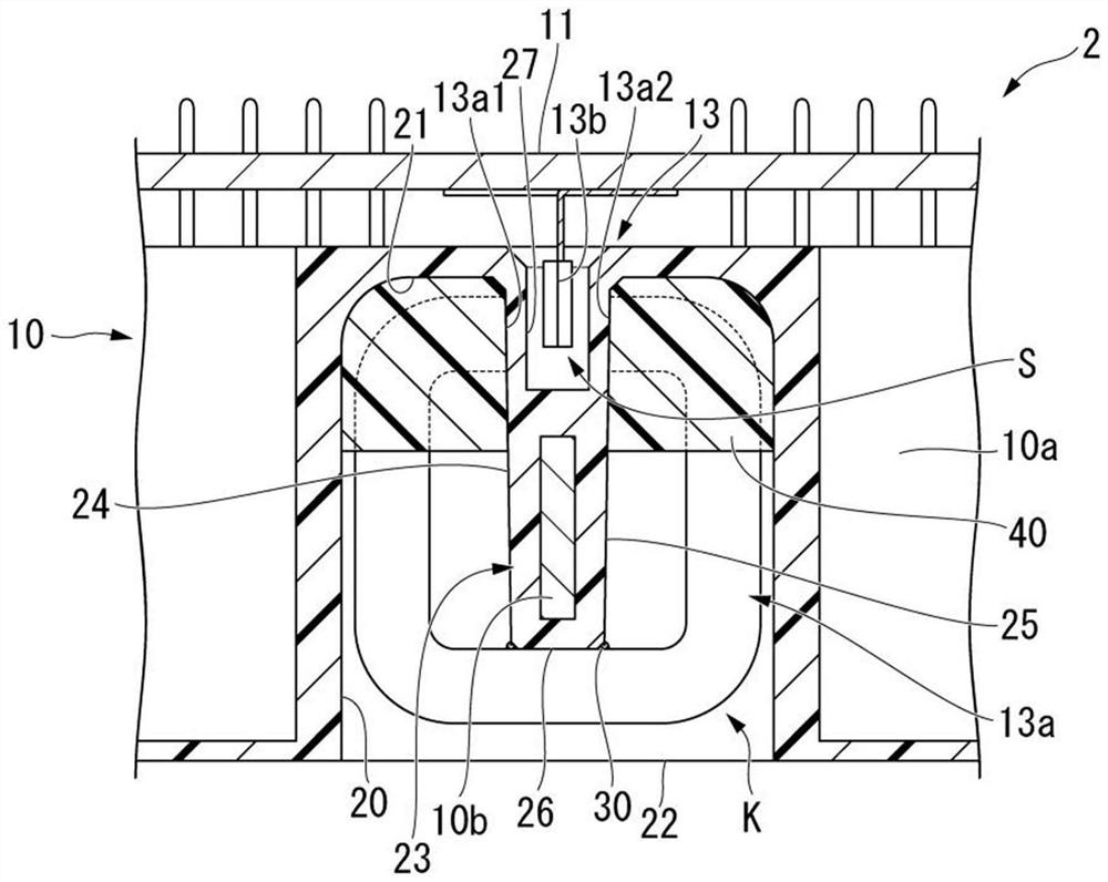
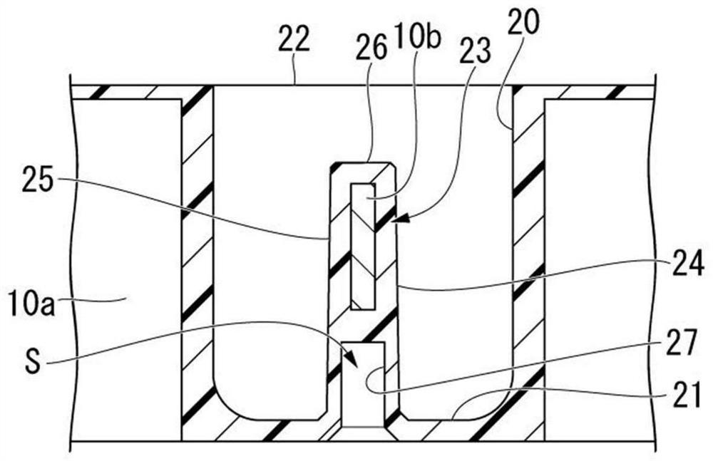
[0026] The intelligent power module 2 includes a power module 10, a circuit board 11, and a current sensor 13 (refer to figure 2 )Wait. The power module 10 includes a plurality of power chips (not shown) having power semiconductor elements, a power module case 10a holding these power chips, and a bus bar 10b connected to the power chips (r...


PUM


Abstract

The invention relates to a power conversion device. This power conversion device is provided with a bus bar through which a current flows, a current sensor having a magnetic core surrounding the bus bar, and a power module case having an accommodating recess for accommodating the magnetic core, and is also provided with an embedded fixture. And an embedding fixture that embeds a portion of the housing recess and fixes the magnetic core to the power module case in a state in which a portion of the magnetic core is exposed.

Description

technical field [0001] The present invention relates to power conversion devices. [0002] This application claims priority based on Japanese Patent Application No. 2019-135860 filed in Japan on July 24, 2019, the contents of which are incorporated herein. Background technique [0003] In vehicles such as electric vehicles, a power conversion device (PCU: Power Control Unit, power control unit) is provided between the battery and the motor. Such a power conversion device includes a plurality of semiconductor power chips and a power module case that houses the power chips. The power module case includes bus bars that serve as electrical paths. Japanese Patent Laid-Open No. 2017-184384 discloses a power conversion device including a current sensor for detecting a current flowing through such a bus bar. [0004] The problem to be solved by the invention [0005] However, the current sensor as described above includes a magnetic core. For example, as shown in Japanese Paten...

Claims


Application Information

Patent Timeline
Patent Type & Authority Applications(China)
IPC IPC(8): H02M1/00H02M7/48
CPCH02M1/00H02M7/48
Inventor 白井隆之灰冈辰训武林贤一野中贤一
Owner HITACHI ASTEMO LTD
Why Eureka
Try Eureka