


Quick Research
Generate reliable direction feasibility study reports for your R&D in just a few steps.

Technical Q&A
Discover and master advanced knowledge NOW. Basics, ideas, possibilities, all at once.

Find Solutions
As an expert in R&D theories, this can generate solutions to your technical problems instantly.

Evaluate Feasibility
Analyze your overall solution with one click, know your potential R&D risks in advance.

Monitor Landscape
Get weekly tech updates, stay abreast of the latest tech innovations and key insights.
Manufacturing method of fluoroplastic insulated power cable
A technology of power cables and manufacturing methods, which is applied in the field of power cables, can solve problems affecting cable production efficiency, low cable yield rate, waste of resources, etc., and achieve the effect of ensuring signal shielding function, improving yield rate, and ensuring insulation performance
- Summary
- Abstract
- Description
- Claims
- Application Information
AI Technical Summary
Problems solved by technology
Method used
Image

Examples
specific Embodiment approach
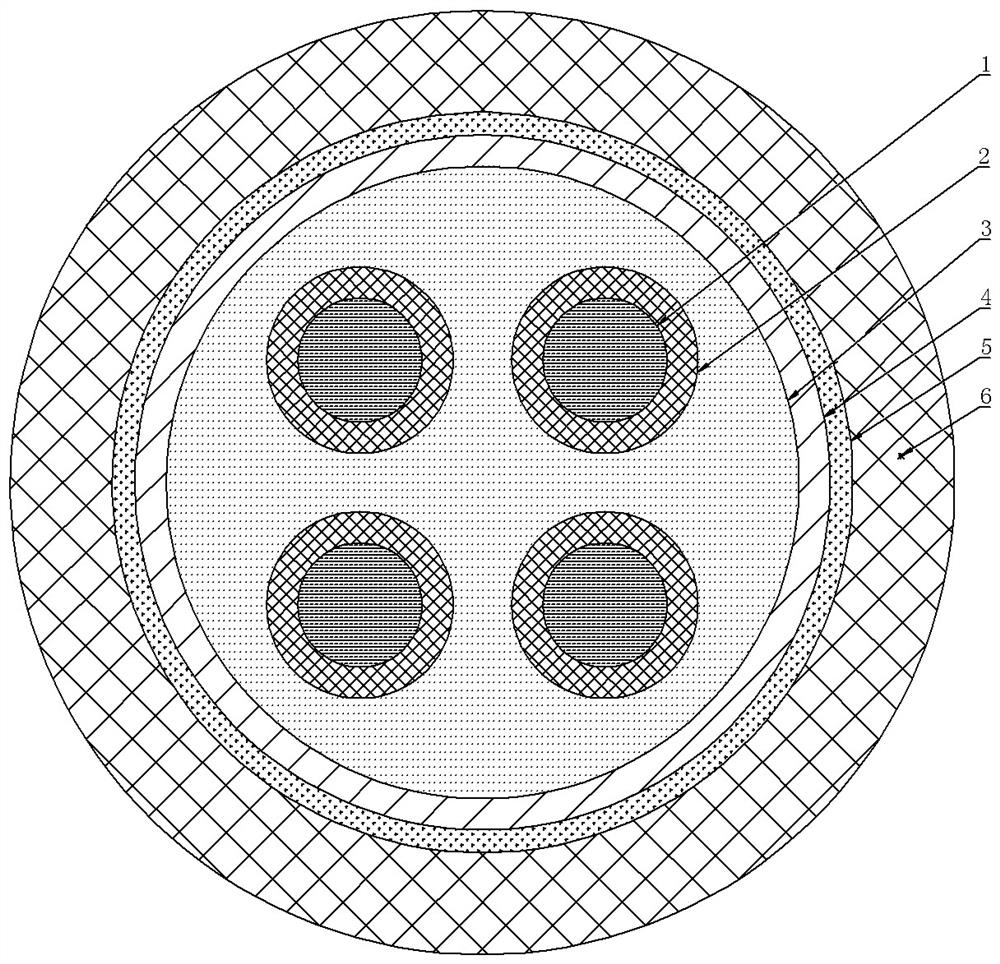
[0019] Specific implementation method: combined figure 1 shown, including the following steps:
[0020] Step 1, drawing and annealing the copper material to form a conductor 1;
[0021] Step 2, without preheating the conductor 1, directly extruding the conductor 1 on the extruder to form the inner insulating layer 2;
[0022] Step 3, conduct a spark test on the conductor 1 with the inner insulating layer 2 after extrusion;
[0023] Step 4: Twisting the conductors 1 that have passed the spark test into a cable core, filling the gaps between multiple cable cores with fillers to form a filling area 3, and tightening all the cores with tape 4;
[0024] Step 5, after tightening the strapping 4, the metal wire is wound on the outer surface of the strapping 4 to form a metal shielding layer 5, and then extruding the outer side of the metal shielding layer 5 on an extruder to form an outer insulating layer 6;
[0025] The inner insulating layer 2 described in step 2 adopts fluorine...
Embodiment 1
[0030] Including the following steps:
[0031] Step 1, drawing and annealing the copper material to form a conductor 1;
[0032] Step 2, without preheating the conductor 1, directly extruding the conductor 1 on the extruder to form the inner insulating layer 2;
[0033] Step 3, conduct a spark test on the conductor 1 with the inner insulating layer 2 after extrusion;
[0034] Step 4: Twisting the conductors 1 that have passed the spark test into a cable core, filling the gaps between multiple cable cores with fillers to form a filling area 3, and tightening all the cores with tape 4;
[0035] Step 5, after tightening the strapping 4, the metal wire is wound on the outer surface of the strapping 4 to form a metal shielding layer 5, and then extruding the outer side of the metal shielding layer 5 on an extruder to form an outer insulating layer 6;
[0036] The inner insulating layer 2 described in step 2 adopts fluorine plastic;
[0037] Step one: the conductor 1 is a solid c...
Embodiment 2
[0041] Including the following steps:
[0042] Step 1, drawing and annealing the copper material to form a conductor 1;
[0043] Step 2, without preheating the conductor 1, directly extruding the conductor 1 on the extruder to form the inner insulating layer 2;
[0044] Step 3, conduct a spark test on the conductor 1 with the inner insulating layer 2 after extrusion;
[0045] Step 4: Twisting the conductors 1 that have passed the spark test into a cable core, filling the gaps between multiple cable cores with fillers to form a filling area 3, and tightening all the cores with tape 4;
[0046] Step 5, after tightening the strapping 4, the metal wire is wound on the outer surface of the strapping 4 to form a metal shielding layer 5, and then extruding the outer side of the metal shielding layer 5 on an extruder to form an outer insulating layer 6;
[0047] The inner insulating layer 2 described in step 2 adopts fluorine plastic;
[0048] Step one: the conductor 1 is a strande...
PUM
 Abstract
Description
Claims
Application Information
 - R&D Engineer
- R&D Manager
- IP Professional
- Industry Leading Data Capabilities
- Powerful AI technology
- Patent DNA Extraction
Browse by: Latest US Patents, China's latest patents, Technical Efficacy Thesaurus, Application Domain, Technology Topic, Popular Technical Reports.
© 2024 PatSnap. All rights reserved.Legal|Privacy policy|Modern Slavery Act Transparency Statement|Sitemap|About US| Contact US: help@patsnap.com