A wave-recording type station area residual current detection terminal and early warning system

A residual current detection terminal technology, applied in the field of power electronics, can solve the problems of frequent leakage, the inability to effectively monitor the instantaneous fault of personal electric shock, and the inability to provide leakage current values, etc.

Active Publication Date: 2021-04-16
南京斯泰恩智慧能源技术有限公司
View PDF10 Cites 0 Cited by
  • Summary
  • Abstract
  • Description
  • Claims
  • Application Information

AI Technical Summary

Problems solved by technology

[0003] The installation of leakage protectors is a common and effective measure to prevent leakage accidents. However, due to irregular design and implementation, and random connections by individuals, frequent leakage occurs, and the total leakage protection cannot be invested. Residents have experienced frequent electric shocks, resulting in results and impacts all bad
[0004] On the other hand, leakage protectors may malfunction or refuse to operate. For example, there are normal small leakage currents in the circuit, such as capacitive leakage currents from long wires to ground, high-power load disconnection or surge voltage caused by lightning. High-order harmonics caused by power electronic equipment may cause misoperation of leakage protectors, causing interruption of residents' power supply, affecting production and life and even causing losses
In addition, current leakage protectors either cannot provide leakage current values, or can only provide steady-state leakage current values, and cannot effectively monitor instantaneous faults such as personal electric shocks.

Method used


Image

  • A wave-recording type station area residual current detection terminal and early warning system
  • A wave-recording type station area residual current detection terminal and early warning system
  • A wave-recording type station area residual current detection terminal and early warning system

Examples


Embodiment Construction

[0024] The present invention will be further explained below in conjunction with the accompanying drawings and specific embodiments. It should be understood that these embodiments are only used to illustrate the present invention and are not intended to limit the scope of the present invention. After reading the present invention, those skilled in the art all fall into the appended claims of the present application to the amendments of various equivalent forms of the present invention limited range.

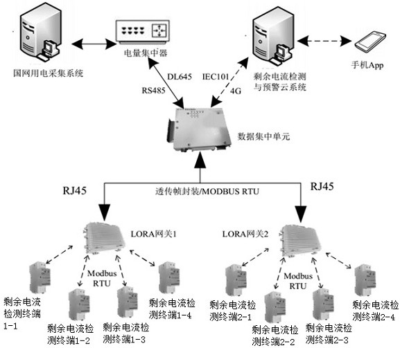
[0025] Such as figure 1 As shown, it is a schematic diagram of the topological network structure of the wave-recording type station area residual current detection and early warning system of the present invention, which is mainly divided into three layers, wherein:

[0026] The first layer consists of a residual current detection terminal and a LORA gateway: the detection terminal detects and calculates user current, voltage, and leakage current data, and the LORA gateway colle...


PUM


Abstract

The invention discloses a wave-recording type station area residual current detection terminal and an early warning system. The terminal includes a residual current detection sampling module, a signal op-amp module, an MCU control module, a metering unit module, a LoRa communication module, and an indication display unit module , an alarm unit module and a storage module. The present invention has voltage, current and residual current measurement functions, and can monitor the residual current of the device under test in real time. By comparing with the set value, an alarm is generated, uploaded to the cloud server through the wireless network and sent push to the user. At the same time, the system has a fault wave recording function, which records the voltage and residual current waveforms of the set period before and after the fault, providing a basis for fault type judgment. The LoRa wireless communication adopted in the present invention reduces the system level, optimizes the transmission mode, and the abnormal data upload breakpoint rate in the station area drops by more than 72.6%.

Description

technical field [0001] The invention belongs to the technical field of power electronics, and in particular relates to the detection technology of residual current in a station area. Background technique [0002] In low-voltage distribution lines, residual current (commonly known as leakage current) is the current leakage caused by insulation damage, irregular wiring, and unreasonable design. If there is a certain potential difference between the electrical casing and the live wire and the ground for some reason, leakage will occur. Leakage is a common fault in low-voltage power distribution networks. It is an important fault that affects the reliability and safety of power supply. Its occurrence affects the reliability of power supply. In severe cases, it endangers the personal safety of users. It is a type of fault that needs to be paid enough attention to. . [0003] The installation of leakage protectors is a common and effective measure to prevent leakage accidents. H...

Claims


Application Information

Patent Timeline
Patent Type & Authority Patents(China)
IPC IPC(8): G01R31/56G01R31/52G01R19/165
CPCG01R19/16571G01R19/16576G01R31/52G01R31/56
Inventor 黄建华刘兵
Owner 南京斯泰恩智慧能源技术有限公司
Why Eureka
Try Eureka