Eureka AIR delivers breakthrough ideas for toughest innovation challenges, trusted by R&D personnel around the world.

Weighing and pressurizing device arranged on on-line friction belt conveyor

A booster device and weighing device technology, applied in the direction of conveyor control devices, conveyors, conveyor objects, etc., can solve the problems of insufficient output traction, increased conveyor belt tension, and conveyor belt slippage, etc., to achieve convenient maintenance, Effect of reduced wear and low cost

Pending Publication Date: 2021-02-02
TAIYUAN UNIVERSITY OF SCIENCE AND TECHNOLOGY
View PDF0 Cites 0 Cited by
  • Summary
  • Abstract
  • Description
  • Claims
  • Application Information

AI Technical Summary

Problems solved by technology

During the transportation process of the online friction belt conveyor, the intermediate drive and the main engine rely on the friction between the belts to transmit traction, and the magnitude of the traction largely depends on the amount of materials. When there is insufficient or no material on the intermediate drive section In some cases, the output traction force of the intermediate drive is not enough, which will lead to an increase in the tension of the conveyor belt of the main engine, and in severe cases, it may cause the conveyor belt to slip or even cause a safety accident. However, there is no solution to this problem in the existing technical solutions

Method used


Image

  • Weighing and pressurizing device arranged on on-line friction belt conveyor
  • Weighing and pressurizing device arranged on on-line friction belt conveyor
  • Weighing and pressurizing device arranged on on-line friction belt conveyor

Examples


Embodiment Construction

[0026] In order to make the technical problems, technical solutions and beneficial effects to be solved by the present invention clearer, the present invention will be further described in detail below in conjunction with the accompanying drawings and embodiments. It should be understood that the specific embodiments described here are only used to explain the present invention, not to limit the present invention.

[0027] It should be noted that when an element is referred to as being “fixed” or “disposed on” another element, it may be directly on the other element or be indirectly on the other element. When an element is referred to as being "connected to" another element, it can be directly connected to the other element or indirectly connected to the other element.

[0028] It is to be understood that the terms "length", "width", "top", "bottom", "front", "rear", "left", "right", "vertical", "horizontal", "top", The orientation or positional relationship indicated by "bot...


PUM


Abstract

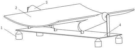
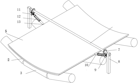
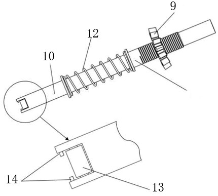
The invention discloses a weighing and pressurizing device arranged on an on-line friction belt conveyor. According to a method, two sets of weighing devices and a set of pressurizing device are included, and the pressurizing device is fixed between the two sets of weighing devices; each weighing device comprises a conveying belt, carrier rollers and the like, wherein the carrier rollers are arranged below the conveying belt, a bearing plate is arranged below the carrier rollers, and weighing sensors are arranged below the bearing plate; and the pressurizing device is composed of an upper cross beam and two end structures, the upper cross beam is arranged above the conveying belts, the two end structures are the same and are symmetrically arranged,each end structure is composed of a supporting frame, an upper gear and the like, each supporting frame is provided with horizontal holes and inclined holes, the upper cross beam penetrates through the horizontal holes, the upper gears penetrate through the upper cross beam, one end of a long round pipe penetrates through the inclined holes, the other end of the long round pipe is in contact with the side edges of the conveying belts, a sleeve penetrates through the long round pipe, lower gears are meshed with the upper gears, a spring sleeves the long round pipe, one end of the spring makes contact with the sleeve, and the other endof the spring makes contact with with a protruding baffle of the long round pipe. The tension of the conveying belts can be controlled, the cost is low, and maintenance is convenient.

Description

technical field [0001] The invention belongs to the technical field of belt conveyors, and in particular relates to a weighing and boosting device arranged on an online friction belt conveyor. Background technique [0002] With the continuous development of the modern mining industry, people pay more and more attention to the development of belt conveyors, especially for the long-distance and large-volume transportation requirements. When using belt conveyors for long-distance transportation, one of the applied solutions Is the use of line friction intermediate belt drives in conveyor construction. During the transportation process of the online friction belt conveyor, the intermediate drive and the main engine rely on the friction between the belts to transmit traction, and the magnitude of the traction largely depends on the amount of materials. When there is insufficient or no material on the intermediate drive section In some cases, the output traction force of the inte...

Claims


Application Information

Patent Timeline
Patent Type & Authority Applications(China)
IPC IPC(8): B65G23/44B65G39/04B65G43/08B65G15/60B65G15/32G01G19/62
CPCB65G15/32B65G15/60B65G23/44B65G39/04B65G43/08G01G19/62
Inventor 姚艳萍姚鑫奇韩刚
Owner TAIYUAN UNIVERSITY OF SCIENCE AND TECHNOLOGY
Why Eureka
Eureka Blog
Learn More