
Shockproof flow instrument and apparatus storage equipment

A technology of instrumentation and equipment, which is applied in the field of shockproof flow instrumentation storage equipment, can solve the problems of flowmeter offset, measurement liquid deviation, pipeline jitter, etc., and achieve the effect of avoiding excessive jitter

Inactive Publication Date: 2021-02-02
王蕾蕾
View PDF0 Cites 4 Cited by
  • Summary
  • Abstract
  • Description
  • Claims
  • Application Information

AI Technical Summary

Problems solved by technology

[0003] Based on the discovery of the above inventors, the existing shockproof flow meter storage equipment mainly has the following deficiencies, such as: when the flow rate of the liquid in the pipeline is too large, the liquid hits the pipe wall, which will cause the pipeline to vibrate, making the installation The flow meter on the pipeline also jitters, causing the flowmeter to deviate in the pipeline, resulting in a deviation in the measurement of the liquid passing through the pipeline

Method used


Image

  • Shockproof flow instrument and apparatus storage equipment
  • Shockproof flow instrument and apparatus storage equipment
  • Shockproof flow instrument and apparatus storage equipment

Examples


Embodiment 1

[0026] Example 1: Please refer to Figure 1-Figure 5 , the specific embodiments of the present invention are as follows:

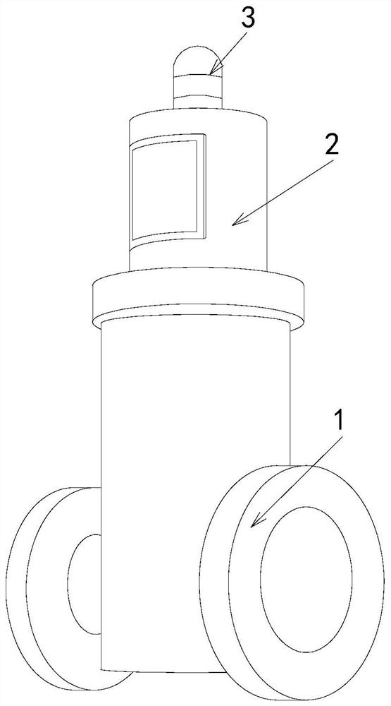
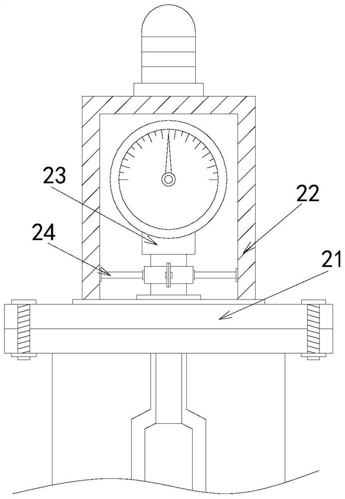
[0027] Its structure includes a flow pipe 1, a storage device 2, and a warning light 3. The upper end of the flow pipe 1 is flange-connected with a storage device 2. The warning light 3 is installed in the middle of the top of the storage device 2. The storage device 2 Including a mounting seat 21, a shockproof cover 22, a meter 23, and a buffer device 24, the upper end surface of the mounting seat 21 is embedded with a shockproof cover 22, and the meter 23 is arranged in the middle of the shockproof cover 22, and the buffer device 24 will Meter 23 supports.

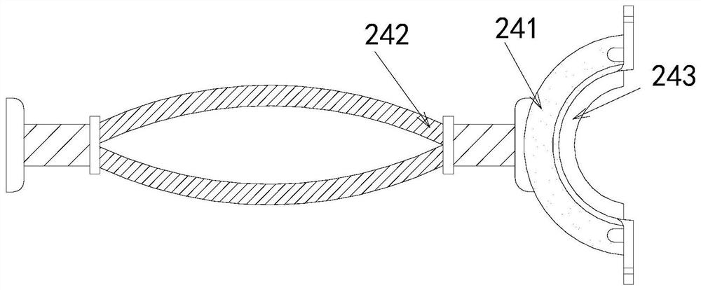
[0028] The buffer device 24 includes a clamp 241, an elastic piece 242, and a limit block 243. The end surface of the clamp 241 is arc-shaped, and the elastic piece 242 is embedded in the rear end of the clamp 241. The limit block 243 is located at In the middle of the front end of the clamp 241, t...

Embodiment 2

[0032] Example 2: Please refer to Figure 6-Figure 8 , the specific embodiments of the present invention are as follows:

[0033] The limit block 243 includes a mounting seat b1, a rubber block b2, a reset groove b3, and a shock absorbing groove b4. The outer end surface of the mounting seat b1 is provided with a rubber block b2, and the upper and lower ends of the rubber block b2 are provided with reset Groove b3, the reset groove b3 is arc-shaped, and more than four shock absorbing grooves b4 are arranged on the outer end surface of the rubber block b2 laterally. The shock absorbing groove b4 is triangular in shape, which is beneficial for the instrument When 23 bumps up and down, the instrument 23 can be buffered through the deformation of the shock absorbing groove b4.

[0034] The reset groove b3 includes an iron sheet b31, a support seat b32, and a guide groove b33. There are two iron sheets b31 located at the upper and lower ends of the reset groove b3, and more than f...


PUM


Abstract

The invention discloses shockproof flow instrument and meter storage equipment. The shockproof flow instrument and meter storage equipment structurally comprises a circulation pipe, storage equipmentand an alarm lamp, wherein the upper end of the circulation pipe is in flange connection with the storage equipment, the alarm lamp is installed in the middle of the top of the storage equipment, thestorage equipment comprises an installation base, a shockproof cover, an instrument and a buffer device, and the buffer device comprises a clamp, elastic pieces and a limiting block, the clamp comprises a supporting layer, a rubber block, a cavity and a buffer strip, and the buffer strip comprises a buffer body, an empty groove and a deformation groove. According to the shockproof flow instrumentand apparatus storage equipment, elasticity generated between the elastic pieces is used for driving the clamp to clamp an instrument, the amplitude of shaking of the instrument along with the circulation pipe can be reduced, the situation that the amplitude of shaking once is too large is avoided, and therefore, the flow detection of the instrument does not have an overlarge error.

Description

technical field [0001] The invention relates to the field of flow instruments, in particular to a shockproof storage device for flow instruments. Background technique [0002] With the development of industry, the requirements for the accuracy and range of flow measurement are getting higher and higher. In order to adapt to various purposes, various types of flowmeters have come out one after another, and are widely used in oil and gas, petrochemical, water treatment, food and beverage, Industries such as pharmaceuticals, energy, metallurgy, pulp and paper, and building materials. [0003] Based on the discovery of the above inventors, the existing shockproof flow meter storage equipment mainly has the following deficiencies, such as: when the flow rate of the liquid in the pipeline is too large, the liquid hits the pipe wall, which will cause the pipeline to vibrate, making the installation The flow meter on the pipeline also jitters, causing the flowmeter to deviate in th...

Claims


Application Information

Patent Timeline
Patent Type & Authority Applications(China)
IPC IPC(8): B65D25/10B65D81/107B65D85/38
CPCB65D25/101B65D81/1075B65D85/38
Inventor 王蕾蕾
Owner 王蕾蕾
Learn More