Automatic torsion type oil pipe coating device

A coating device and oil pipe technology, which can be applied to cleaning hollow objects, chemical instruments and methods, cleaning methods and utensils, etc., can solve the problems of larger pipe diameter at the bend of the oil pipe, cumbersome manual winding process, and large amount of use.

Inactive Publication Date: 2021-02-02
陈映楠
View PDF0 Cites 3 Cited by
  • Summary
  • Abstract
  • Description
  • Claims
  • Application Information

AI Technical Summary

Problems solved by technology

[0005] In order to overcome the subsequent bending process of the automobile oil pipe in the prior art, it is necessary to bend the automobile oil pipe in different degrees and at different positions according to the needs of different vehicles, and the obtained oil pipe has an irregular shape. Before use, it is necessary to cover the surface of the tubing with rubber to prevent the tubing from being scratched by external forces and oxidized by air in the later stage. Manual rubber winding is often used for this kind of tubing. In the process of manual rubber winding, the length of the tubing is longer and manual The winding process is cumbersome, and at the bend of the oil pipe, in order to ensure the flatness and tightness of the rubber, it is often necessary to carry out multi-layer winding and covering, resulting in a large amount of rubber used at the bend, and at the same time, the thickness of the multi-layer rubber is large after stacking. The diameter of the oil pipe at the bend becomes larger, which affects the shortcoming of subsequent installation and use. The technical problem is: to provide an automatic twisting type oil pipe coating device

Method used


Image

  • Automatic torsion type oil pipe coating device
  • Automatic torsion type oil pipe coating device
  • Automatic torsion type oil pipe coating device

Examples


Embodiment 1

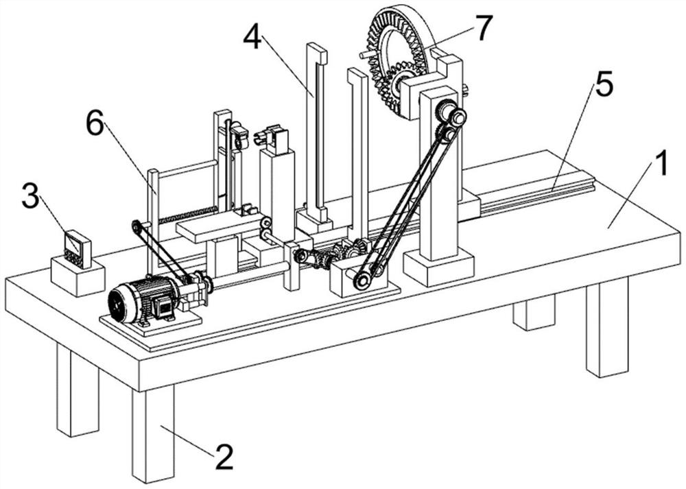
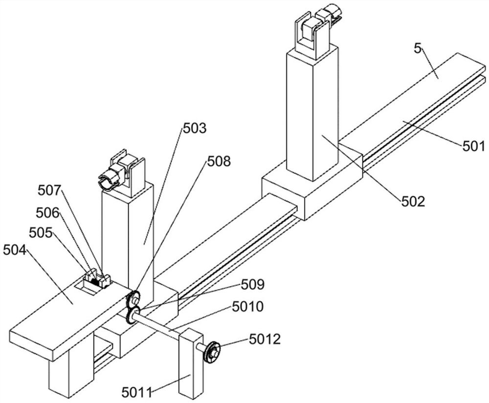
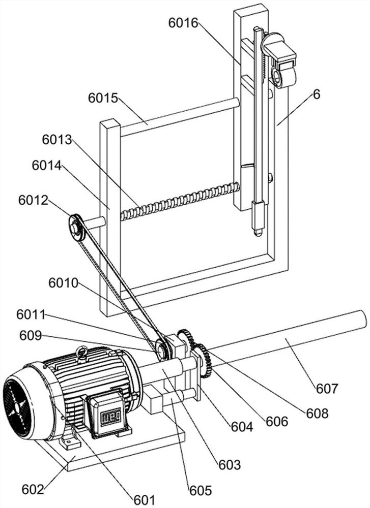
[0028] An automatic twisting oil pipe coating device, such as Figure 1-7 As shown, it includes a working machine board 1, a supporting foot 2, an operation control panel 3, a laser scanning detection door 4, a fixed alignment mechanism 5, a surface treatment mechanism 6, and a covering mechanism 7; the lower part of the working machine board 1 and the supporting bottom The feet 2 are welded; the operation control panel 3 is arranged above the working machine board 1; the upper part of the working machine board 1 is connected with the laser scanning detection door 4; It is connected with the surface treatment mechanism 6; the upper part of the machine tool plate 1 is connected with the coating mechanism 7; the coating mechanism 7 is connected with the surface treatment mechanism 6; the surface treatment mechanism 6 is connected with the fixed normal position mechanism 5; the fixed normal position mechanism 5 is connected with covering mechanism 7.

[0029] When using the auto...


PUM


Abstract

The invention relates to the field of automobile fluid pipelines, in particular to an automatic torsion type oil pipe coating device. The technical problem is to provide the automatic torsion type oilpipe coating device. According to the technical scheme, the automatic torsion type oil pipe coating device comprises a working machine bed board, supporting bottom feet, an operation control screen,a laser scanning detection door, a fixing and aligning mechanism, a surface treatment mechanism and a coating mechanism; and the lower portion of the working machine bed board is welded to the supporting bottom feet. According to the automatic torsion type oil pipe coating device, automatic torsion and direction changing can be carried out, so that an oil pipe with a bent shape can be automatically wiped in a mode that the device is attached to the irregular surface of the oil pipe before rubber wrapping, and meanwhile, horizontal aligning and vertical positioning are sequentially carried outduring fixing, so that the oil pipe is always located in the winding center in the rubber wrapping process, the compactness and the firmness of rubber wrapping are guaranteed, and the effect of automatically wrapping the rubber by replacing manual work is achieved.

Description

technical field [0001] The invention relates to the field of automobile fluid pipelines, in particular to an automatic twisting oil pipe coating device. Background technique [0002] There are various fluid pipelines in fuel vehicles, including various oil pipes. Among them, there is a metal oil pipe. In order to adapt to the assembly of parts inside the car, this oil pipe has irregular pipelines and various bent pipes. [0003] At present, during the subsequent bending process of the automobile oil pipe in the prior art, it is necessary to bend the automobile oil pipe in different degrees and at different positions according to the needs of different vehicles, and the obtained oil pipe has an irregular shape. Before use, it is necessary to cover the surface of the tubing with rubber to prevent the tubing from being scratched by external forces and oxidized by air in the later stage. Manual rubber winding is often used for this kind of tubing. In the process of manual rubber...

Claims


Application Information

Patent Timeline
IPC IPC(8): B29C63/02B29C63/00B29C63/48B29C31/08B08B9/023
CPCB08B9/023B29C31/002B29C31/08B29C63/0004B29C63/0073B29C63/02B29C63/481
Inventor 陈映楠
Owner 陈映楠
Why Eureka
Try Eureka