
Biological filtration waste gas removal equipment

A biological filtration and waste gas technology, applied in the fields of dispersed particle filtration, dispersed particle separation, chemical instruments and methods, etc., can solve the problems of reduced waste gas filtration effect, thinner filter screen thickness, toxic and harmful gases, etc. The effect of reducing corrosion and reducing endurance

Inactive Publication Date: 2021-02-02
赵乐洋
View PDF0 Cites 5 Cited by
  • Summary
  • Abstract
  • Description
  • Claims
  • Application Information

AI Technical Summary

Problems solved by technology

[0002] Since the gas emitted by human beings in the process of life and production is poisonous and harmful, it is necessary to filter the gas generated by production. In order to filter the pollutants in the gas more completely, biological filtration equipment is often used to remove waste gas, and the waste gas is passed into the filter tower. Internally, it is discharged after being filtered by the filter screen inside the tower; in the process of filtering the exhaust gas by using biological filtration exhaust gas removal equipment in the prior art, when the exhaust gas contains sulfur dioxide substances, the sulfur dioxide substances are blocked on the outer layer of the filter screen, and the incoming The gas contains oxygen and water molecules. Sulfur dioxide reacts with oxygen and water molecules to form sulfuric acid, which is corrosive. When sulfuric acid stays on the outer layer of the filter, the filter is corroded by sulfuric acid, and the thickness of the filter gradually becomes thinner. Reduced filtering effect on exhaust gas

Method used


Image

  • Biological filtration waste gas removal equipment
  • Biological filtration waste gas removal equipment
  • Biological filtration waste gas removal equipment

Examples


Embodiment 1

[0027] as attached figure 1 to attach Figure 5 Shown:

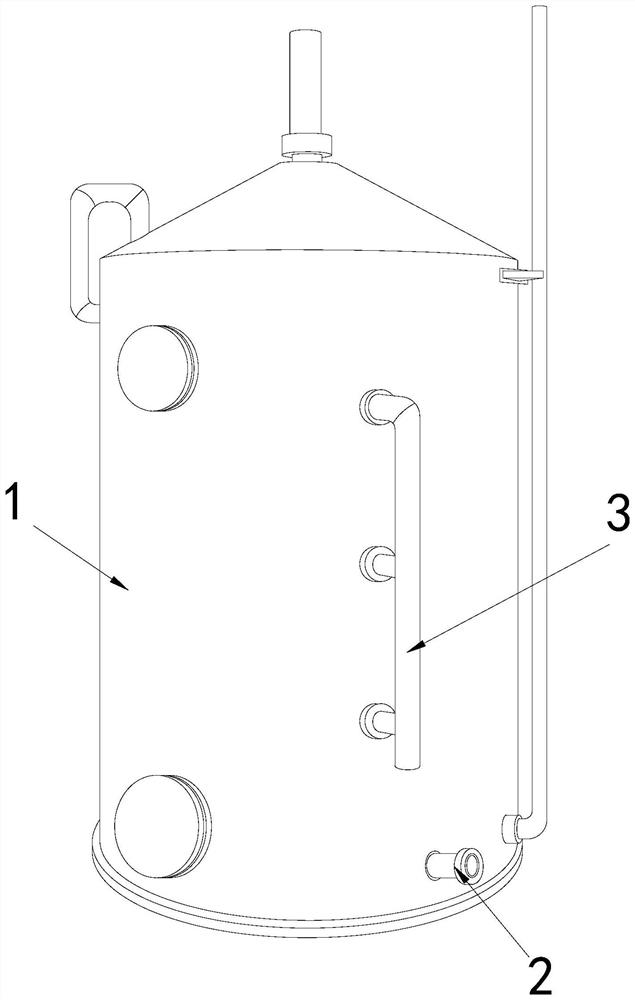
[0028] The present invention provides a kind of biological filtration waste gas removal equipment, its structure includes a tower body 1, a discharge pipe 2, and an air intake pipe 3, the discharge pipe 2 is horizontally welded at the bottom end of the front of the tower body 1, and the air intake pipe 3 is installed on The front of the tower body 1 is on the right side.

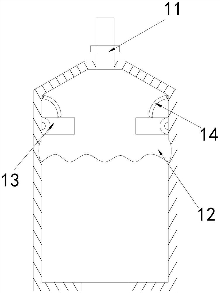
[0029] The tower body 1 is provided with an exhaust pipe 11, a filter screen 12, a push mechanism 13, and a push bar 14. The exhaust pipe 11 runs through the center of the top of the tower body 1, and the filter screen 12 is set in the inner wall of the tower body 1. In the upper position, the pushing mechanism 13 is installed on the inner wall of the tower body 1 and above the filter screen 12 , and the push bar 14 is installed between the top of the pushing mechanism 13 and the inner wall of the tower body 1 .

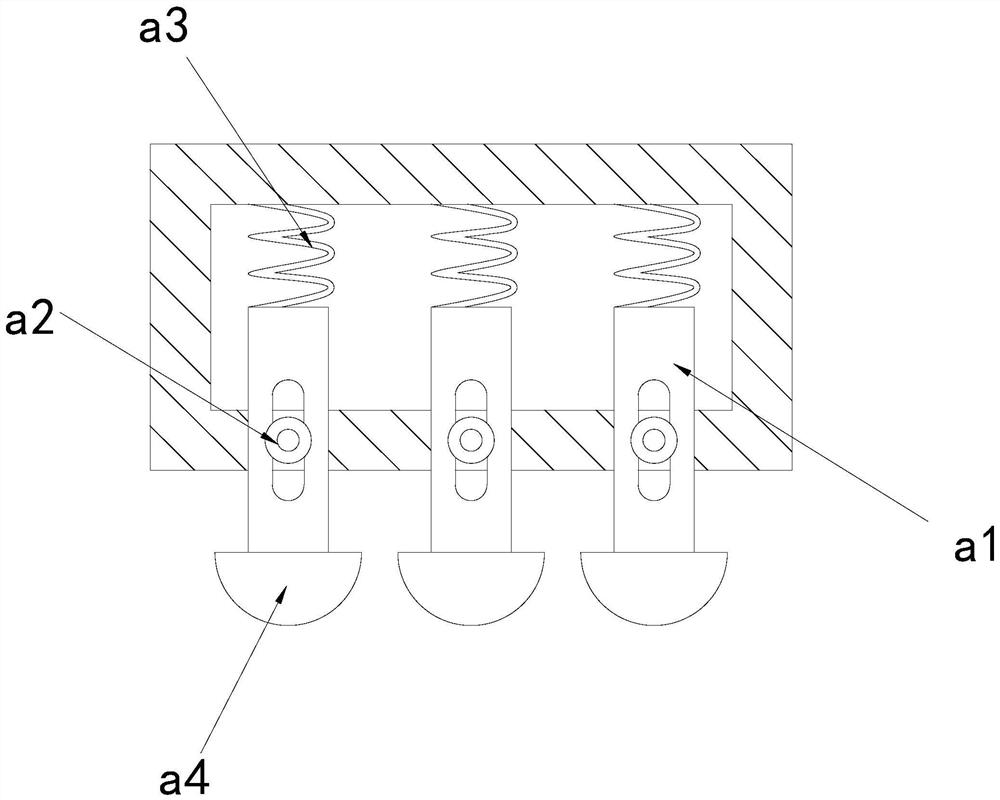
[0030] Wherein, the pushing mechani...

Embodiment 2

[0036] as attached Figure 6 to attach Figure 7 Shown:

[0037] Wherein, the clamping block s3 is provided with a support block e1, a slot e2, a push rod e3, and an elastic bar e4, the slot e2 is located inside the two sides of the support block e1, and the push rod e3 passes through the bottom of the slot e2 Cooperating with the elastic strip e4, the side of the push rod e3 is arc-shaped, which is beneficial to fully cooperate with the inner side of the swing plate s2.

[0038] Wherein, the push rod e3 is provided with a support frame r1, a swing rod r2, a reset bar r3, and a scraper r4, the swing rod r2 is installed on the left side of the support frame r1, and the reset bar r3 is clamped on the left end of the swing rod r2 Between the bottom surface and the inner wall on the right side of the support frame r1, the scraper r4 is fixed on the right end of the swing rod r2, and the reset bar r3 is made of rubber material with elasticity, which is beneficial to drive the swi...


PUM


Abstract

The invention discloses biological filtration waste gas removal equipment which structurally comprises a tower body, a discharge pipe and a gas inlet pipe, the discharge pipe is horizontally welded atthe bottom end of the front surface of the tower body, the gas inlet pipe is mounted in the right side of the front surface of the tower body, and when sulfuric acid is retained on the outer layer ofa filter screen, the filter screen is corroded by sulfuric acid, so that the thickness of the filter screen is gradually reduced; a pushing mechanism swings up and down under the pushing force of waste gas to push and vibrate the filter screen, sulfur dioxide substances retained on the outer wall of the filter screen shake and fall off, sulfuric acid generated by reaction of the sulfur dioxide substances, water molecules and oxygen is reduced, corrosion of the filter screen is reduced, the filter screen can fully filter the waste gas, as water molecules in waste gas cannot be completely filtered and absorbed by the filter screen and are easily retained on the inner side of the swing plate, the water molecules on the inner side of the swing plate are removed by the blades after the swing plate swings and resets, the bearing force of the swing plate is favorably reduced, the swing speed of the swing plate is increased, and the push vibration of the filter screen is accelerated.

Description

technical field [0001] The invention belongs to the field of biological filtration equipment, and more specifically relates to a biological filtration waste gas removal equipment. Background technique [0002] Since the gas emitted by human beings in the process of life and production is poisonous and harmful, it is necessary to filter the gas generated by production. In order to filter the pollutants in the gas more completely, biological filtration equipment is often used to remove waste gas, and the waste gas is passed into the filter tower. Internally, it is discharged after being filtered by the filter screen inside the tower; in the process of filtering the exhaust gas by using biological filtration exhaust gas removal equipment in the prior art, when the exhaust gas contains sulfur dioxide substances, the sulfur dioxide substances are blocked on the outer layer of the filter screen, and the incoming The gas contains oxygen and water molecules. Sulfur dioxide reacts wi...

Claims


Application Information

Patent Timeline
Patent Type & Authority Applications(China)
IPC IPC(8): B01D46/10B01D46/00
CPCB01D46/10B01D46/76
Inventor 赵乐洋
Owner 赵乐洋
Learn More