
Pressure limiting valve and cooking utensil

A pressure-limiting valve and valve seat technology, which is applied in cooking utensils, pressure cookers, household appliances, etc., can solve the problems of complete cold air discharge and difficult cooking utensils, and achieve the effects of stable structure, improved cooking efficiency, and reduced air-conditioning residue

Pending Publication Date: 2021-02-02
ZHEJIANG SHAOXING SUPOR DOMESTIC ELECTRICAL APPLIANCE CO LTD
View PDF0 Cites 1 Cited by
  • Summary
  • Abstract
  • Description
  • Claims
  • Application Information

AI Technical Summary

Problems solved by technology

[0004] The main purpose of the present invention is to provide a pressure limiting valve and a cooking appliance to solve the problem that the pressure limiting valve of the cooking appliance is difficult to completely discharge the cold air in the cooking appliance

Method used


Image

  • Pressure limiting valve and cooking utensil
  • Pressure limiting valve and cooking utensil
  • Pressure limiting valve and cooking utensil

Examples


Embodiment Construction

[0032] It should be noted that, in the case of no conflict, the embodiments in the present application and the features in the embodiments can be combined with each other. The present invention will be described in detail below with reference to the accompanying drawings and examples.

[0033] It should be noted that the terminology used here is only for describing specific implementations, and is not intended to limit the exemplary implementations according to the present application. As used herein, unless the context clearly dictates otherwise, the singular is intended to include the plural, and it should also be understood that when the terms "comprising" and / or "comprising" are used in this specification, they mean There are features, steps, operations, means, components and / or combinations thereof.

[0034] For the convenience of description, spatially relative terms may be used here, such as "on ...", "over ...", "on the surface of ...", "above", etc., to describe the ...


PUM


Abstract

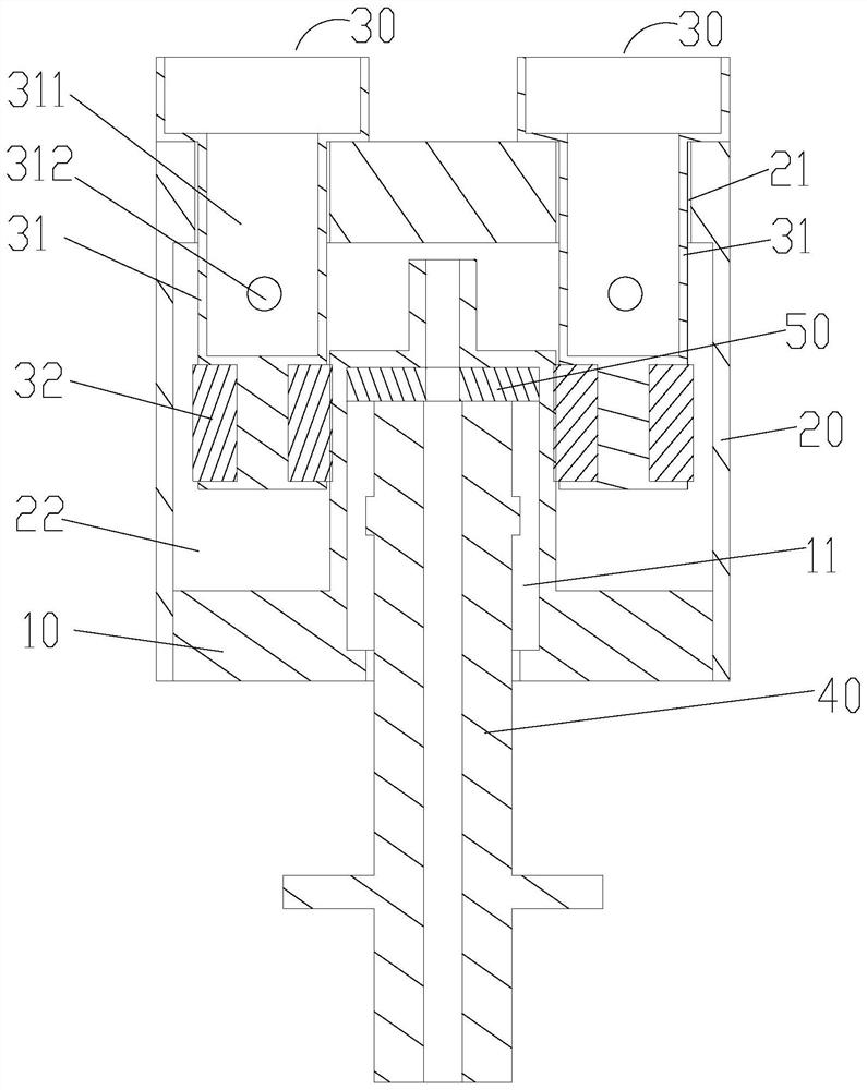
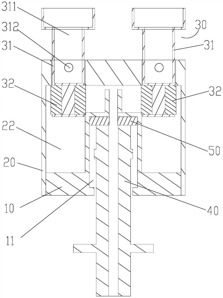
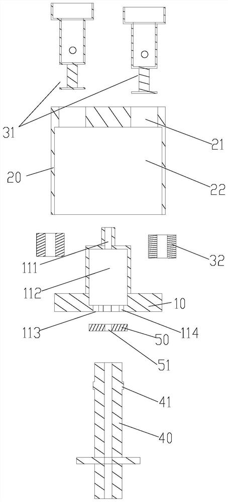
The invention provides a pressure limiting valve and a cooking utensil. The pressure-limiting valve comprises a valve seat provided with an air inlet hole; a valve cover which covers the valve seat, wherein a cavity is defined by the valve cover and the valve seat, at least two mounting holes are formed in the top end of the valve cover, and the mounting holes are communicated with the cavity; andfloat valves, wherein at least two float valves are mounted in the at least two mounting holes in a one-to-one correspondence manner, exhaust channels are formed in the float valves, the float valvesare provided with sealing positions for blocking the mounting holes and exhaust positions for communicating the exhaust channels with the cavities, and the float valves float up and down in the axialdirection of the mounting holes so as to be switched between the sealing positions and the exhaust positions. Due to the fact that the number of the float valves is two or more, each float valve is provided with the corresponding exhaust channel, exhaust is conducted on the cooking utensil through the multiple exhaust channels at the same time, cold air in the cooking utensil can be rapidly exhausted out, cold air residues in the cooking utensil can be effectively reduced, and the cooking efficiency of the cooking utensil is conveniently improved.

Description

technical field [0001] The invention relates to the technical field of household appliances, in particular to a pressure limiting valve and a cooking appliance. Background technique [0002] Electric pressure cooker is an upgraded product of traditional pressure cooker and electric rice cooker. It combines the advantages of pressure cooker and electric rice cooker, completely solves the safety problem of pressure cooker, and relieves the safety hazard that has troubled consumers for many years with ordinary pressure cooker; its thermal efficiency is greater than 80% , save time and electricity. [0003] The existing pressure limiting valve can only seal the exhaust nozzle and keep the pressure in the pot under the working pressure, but after the cold pot of the electric pressure cooker is started and the non-opening valve floats up, the non-opening valve and the pressure-limiting valve are sealed against the inside of the pot. , the remaining part of the cold air is not com...

Claims


Application Information

Patent Timeline
Patent Type & Authority Applications(China)
IPC IPC(8): A47J36/38A47J27/08
CPCA47J36/38A47J27/08
Inventor 张懿豪瞿义
Owner ZHEJIANG SHAOXING SUPOR DOMESTIC ELECTRICAL APPLIANCE CO LTD
Learn More