Hydraulic pressure control unit for saddle-type vehicle brake system and saddle-type vehicle brake system

A riding-type vehicle and control unit technology, applied in the direction of brake control system, ABS control system, brake, etc., can solve the problems of difficult problems, very strict space restrictions on the hydraulic control unit, and difficulty in ensuring the space for the auxiliary plunger, etc., to achieve The effect of matrix compaction

Active Publication Date: 2021-01-29
ROBERT BOSCH GMBH
View PDF8 Cites 2 Cited by
  • Summary
  • Abstract
  • Description
  • Claims
  • Application Information

AI Technical Summary

Problems solved by technology

However, it is difficult to secure a space for the additional auxiliary plunger because the components of the multi-system hydraulic circuit are originally installed on the base body, resulting in the need to extremely increase the size of the hydraulic control unit.
That is, in the conventional brake system for saddle type vehicles, it is difficult to add an auxiliary plunger pump while suppressing the extreme enlargement of the hydraulic control unit.
In addition, in saddled vehicles, compared with other vehicles (for example, automobiles, trucks, etc.), the installation space of the hydraulic control unit is very restricted, so the influence of the difficulty is very large

Method used


Image

  • Hydraulic pressure control unit for saddle-type vehicle brake system and saddle-type vehicle brake system
  • Hydraulic pressure control unit for saddle-type vehicle brake system and saddle-type vehicle brake system
  • Hydraulic pressure control unit for saddle-type vehicle brake system and saddle-type vehicle brake system

Examples


Embodiment approach

[0020] A saddle type vehicle brake system according to an embodiment will be described below.

[0021]

[0022] The configuration and operation of the saddle type vehicle brake system according to the embodiment will be described.

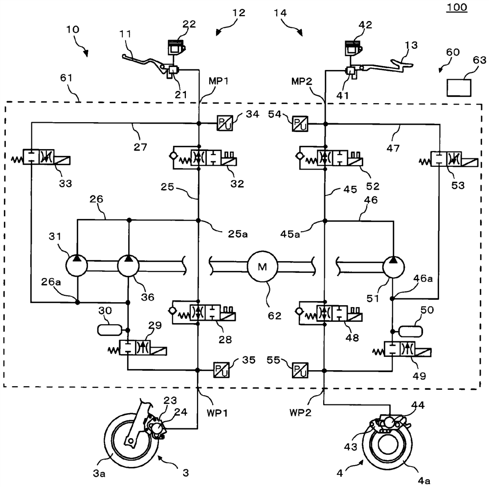
[0023] figure 1 It is a figure which shows the structure of the saddle type vehicle equipped with the brake system for saddle type vehicles which concerns on embodiment of this invention. figure 2 It is a figure which shows the structure of the brake system for saddle type vehicles which concerns on embodiment of this invention.

[0024] Such as figure 1 as well as figure 2 As shown, the saddle type vehicle brake system 10 is mounted on a saddle type vehicle 100 . The saddled vehicle 100 includes: a body 1, a handlebar 2 rotatably held on the body 1, a front wheel 3 rotatably held on the body 1 together with the handlebar 2, and a wheel 2 rotatably held on the body 1. rear wheel 4.

[0025] The saddle type vehicle brake system 10 includes...


PUM


Abstract

To acquire a hydraulic pressure control unit (60) and a straddle-type vehicle brake system (10) capable of adding an auxiliary plunger pump (36) while suppressing extreme enlargement of the hydraulicpressure control unit (60). In a base body (61), a combination of a first plunger pump (31) and a first accumulator (30) and a combination of a second plunger pump (51) and a second accumulator (50) for a different system of a hydraulic circuit therefrom are separately provided on both sides of a reference surface (P) including a center axis (C) of a motor hole (71). A first plunger pump hole (72)and a second plunger pump hole (73) are separately provided on a second surface (61b) and a third surface (61c) constituting both ends of the base body (61) in a first direction (Dl). A first accumulator hole (74), a second accumulator hole (75), and an auxiliary plunger pump hole (93) are provided on a fourth surface (61d) constituting an end of the base body (61) in a second direction (D2).

Description

technical field [0001] The present invention relates to a hydraulic control unit of a brake system for a saddle-type vehicle, and a brake system for a saddle-type vehicle equipped with the hydraulic control unit. Background technique [0002] There is known a hydraulic control unit for operating a saddle-type vehicle brake system to perform anti-lock braking operations. The hydraulic control unit includes a base body, and the base body is formed with: a master cylinder port connected to a liquid pipe of a master cylinder of a brake system for a saddle-type vehicle; The liquid pipes of the wheel cylinders of the system are connected; the main flow path communicates the master cylinder port and the wheel cylinder port through the inflow valve; the sub flow path is used to release the brake fluid in the wheel cylinder to the master cylinder through the outflow valve. An accumulator and a plunger pump are provided in this order from the upstream side in the sub flow path. In a...

Claims


Application Information

Patent Timeline
Patent Type & Authority Applications(China)
IPC IPC(8): B60T8/36
CPCB60T8/3225B60T8/368B60T8/4031B60T13/145B60T15/028B60T17/02B60T17/04B60T2270/10B60T2270/402
Inventor 下山耕作
Owner ROBERT BOSCH GMBH
Why Eureka
Try Eureka