Compressor bleed structure and aero-engine

A technology of air compressor and air port, which is applied in the direction of machine/engine, engine components, engine cooling, etc. It can solve the problems of reducing the efficiency of bleed air, setting up flow guide devices, and difficult drum walls, etc., so as to reduce the flow loss of bleed air, Effects of improving mechanical strength, improving bleed air efficiency and bleed air stability and reliability

Active Publication Date: 2021-03-19
AECC SHANGHAI COMML AIRCRAFT ENGINE MFG CO LTD +1
View PDF5 Cites 0 Cited by
  • Summary
  • Abstract
  • Description
  • Claims
  • Application Information

AI Technical Summary

Problems solved by technology

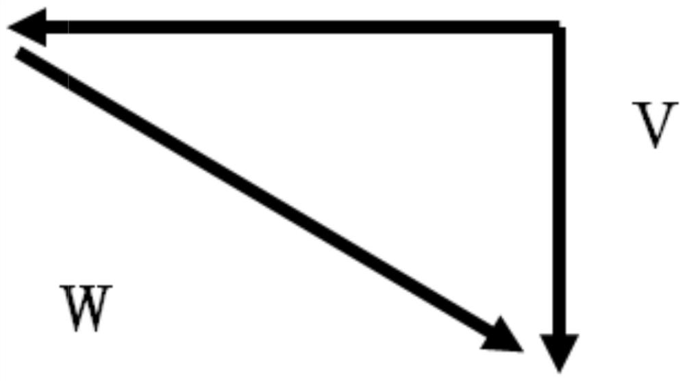
[0003] 1. The air-introduction ports on the drum wall are usually set in the form of through holes and are distributed at intervals along the circumferential direction. Since the air-induction ports rotate with the rotor, the air flow at the air-induction ports has a high circumferential implicated velocity, and the form of vertical through-holes is adopted. , the relative velocity of the bleed air does not match the angle of the air outlet, which will cause a large airflow impact loss, thereby reducing the bleed air efficiency;
[0004] 2. The drum wall is usually thin, and it is difficult to install a flow guide device on the drum wall

Method used


Image

  • Compressor bleed structure and aero-engine
  • Compressor bleed structure and aero-engine
  • Compressor bleed structure and aero-engine

Examples


Embodiment Construction

[0030] Various exemplary embodiments of the present disclosure will now be described in detail with reference to the accompanying drawings. The description of the exemplary embodiments is illustrative only, and in no way restricts the disclosure, its application or uses. The present disclosure can be implemented in many different forms and is not limited to the examples herein. Rather, these embodiments are provided so that this disclosure will be thorough and complete, and will fully convey the scope of the disclosure to those skilled in the art. It should be noted that relative arrangements of parts and steps, compositions of materials, numerical expressions and numerical values ​​set forth in these embodiments should be interpreted as illustrative only and not as limiting, unless specifically stated otherwise.

[0031] "First", "second" and similar words used in the present disclosure do not indicate any order, quantity or importance, but are only used to distinguish diffe...


PUM


Abstract

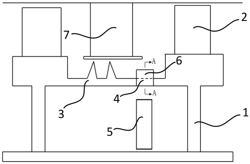
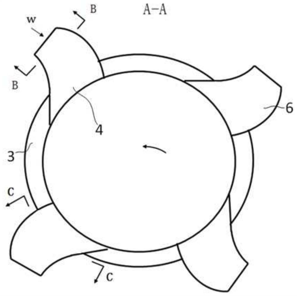
The present disclosure relates to a compressor bleed structure and an aeroengine. Among them, the air-inducing structure of the compressor includes: two-stage rotor discs; two-stage rotor blades; a drum with a plurality of air-inducing ports distributed along the circumferential direction; The drain tubes are arranged on the outer wall of the drum and communicate with the air inlets one by one. The draft tubes are arc-shaped tubes and the offset direction of the stacking axis is configured to be consistent with the rotation direction of the rotor disc. The drainage tube can rectify the turbulent flow field near the air-induction port, and guide the airflow to the air-induction port smoothly. While improving the mechanical strength of the drainage structure, it can effectively reduce the flow loss of the air-induction, and effectively improve the efficiency of the air-induction and the stability and reliability of the air-induction. .

Description

technical field [0001] The disclosure relates to the technical field of gas turbines, in particular to a compressor bleed air structure and an aeroengine. Background technique [0002] In an aero-engine compressor, the rotor-stator part of the turbine with a relatively high operating temperature usually needs to be cooled by introducing cold air from the compressor end with a relatively low operating temperature. Flow through the inner cavity of the rotor to the turbine end, and usually directly open holes on the wall of the rotor drum to guide the cooling air with a certain pressure in the main channel of the compressor to the inner cavity of the rotor, but there are the following problems in this design technology: [0003] 1. The air-introduction ports on the drum wall are usually set in the form of through holes and are distributed at intervals along the circumferential direction. Since the air-induction ports rotate with the rotor, the air flow at the air-induction port...

Claims


Application Information

Patent Timeline
Patent Type & Authority Patents(China)
IPC IPC(8): F04D29/32F04D29/66F02C7/18
CPCF02C7/18F04D29/321F04D29/666F04D29/667
Inventor 王进春郭玲言赞王家广曹传军李游陆晓锋吴志青
Owner AECC SHANGHAI COMML AIRCRAFT ENGINE MFG CO LTD
Why Eureka
Try Eureka