Stranding machine for rubber strip production

A technology of using a plying machine and a rubber strip, applied in textiles and papermaking, auxiliary devices for rope making, textile cables, etc., can solve the problems of reducing overflow and slow processing efficiency, reducing mechanical failures, increasing output, and exchanging convenient products. Effect

Active Publication Date: 2021-01-29
ANHUI ANQING SHASHI AUTO PARTS
View PDF7 Cites 1 Cited by
  • Summary
  • Abstract
  • Description
  • Claims
  • Application Information

AI Technical Summary

Problems solved by technology

[0005] (1) Introduce nylon wire or other insulating materials and rubber strips from the wire splitting teeth through the pay-off 
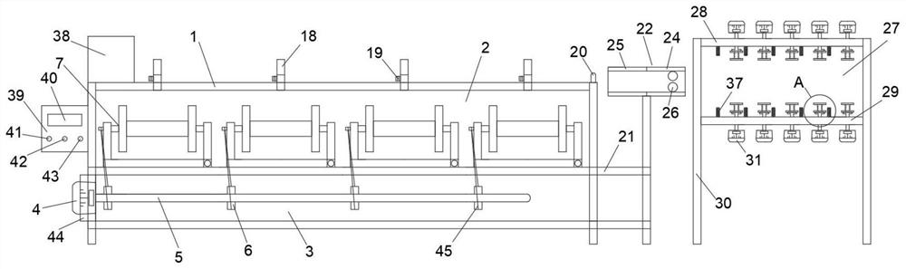
assembly, start the speed-regulating motor, and the speed-regulating motor drives the rotating gear on the rotating shaft to rotate, and the belt on the rotating gear drives the outer belt on the joint assembly. The shaft rotates, and the rotation of the outer shaft drives the nylon wires or other insulating materials on multiple spools to be plied with the rubber strips. Through the above structure settings, in the process of plying the rubber strips, the insulation between the rubber strips and the nylon wires or other insulation materials is effectively improved. The efficiency of material plying avoids the situation that a single spool and can only be plied with a single material, resulting in slow subsequent 
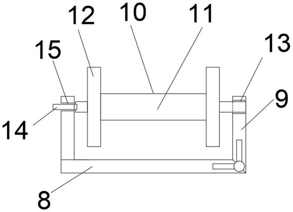
processing efficiency; (2) After the rubber strip and nylon wire or other insulating materials are fully wound on the spool, the swinging block is moved to make The oscillating block hingedly connected by the fixed frame rotates to the right, and the right end of the outer shaft is equipped with a fitting structure that matches the inside of the left end of the bobbin. Move the wire take-up assembly to the right and take it out, replace it with a new wire take-up assembly and install it on the joint assembly , the spool is engaged with the outer shaft in the pipe at the left end of the fixed frame. After moving the wire take-up assembly to the middle of the fixed frame, swing the swing block so that the swing block hingedly connected by the fixed frame turns to the left until the right end of the bobbin meets the inside of the swing block. Through the above-mentioned setting of the take-up assembly, the take-up assembly can be disassembled in time after the nylon wire or other insulating material and the rubber strip are fully rolled, which not only improves the output of the plying machine, but also improves the take-up assembly. When installing, use the left end of the bobbin to connect with the outer shaft, the hinged connection between the swinging block and the fixed frame, and the outer end of the bobbin to fit the hole of the swinging block, which increases the simplicity of the plying machine and reduces the number of rubber strips in the plying machine during the processing of the plywood strips. Mechanical failure caused by overflow after the roll is full; (3) Before the nylon wire or other insulating materials and rubber strips enter the branch teeth, the nylon wires or other insulating materials and rubber strips are introduced into the micro-heating box through the lead shaft in the pay-off assembly At the opening of the right end, the guide wheels at the upper and lower ends of the right side of the micro-heating box make the nylon wire or other insulating materials and rubber strips pull in the middle of the micro-heating box, and the first and second thermal resistance wires at the upper and lower ends of the micro-heating box are aligned. The nylon wire or other insulating materials and rubber strips in the middle are slightly heated. During the slight heating process of nylon wires or other insulating materials and rubber strips, the viscosity of the rubber strips softens and increases, achieving the effect of preliminary joint stock. Through the above structure settings, Slight heating of nylon wire or other insulating materials and rubber strips speeds up the next step of the joint process, which enhances the effect of the joint machine. The wire or other insulating materials and rubber strips move to the middle of the micro-heating box, on the one hand, it solves the problem of uneven heating of the rubber strips, and on the other hand, it facilitates the preliminary jointing of nylon wires or other insulating materials and rubber strips; (4) Pay-off wheel The second groove inside is matched with the second bump of the pay-off shaft. After the nylon wire or other insulating materials and rubber strips are placed, the pay-off wheel can be replaced, which makes it easy to replace the pay-off wheel and improves the release speed. Line efficiency, to further improve the efficiency of the jointing machine, the stop pad on one side of the pay-off shaft is elastic, and during the pay-off process, the stop pad blocks one end of the pay-off wheel, avoiding the winding accident caused by the vibration of the pay-off wheel. Through the driving motor on one side of the upper pay-off plate or the lower pay-off plate, the pay-off mode is changed to active pay-off, which reduces the force of the pay-off wheel on the reel wheel and the bobbin; (5) Nylon wire or other insulating materials After passing through the splitting teeth with the rubber strip, it winds around the lead wheel and the rerouting wheel and enters the bobbin for plying and winding. The interval between each lead wheel of the lead wheel group on the top of the upper shelf increases gradually from left to right, so that the rubber strip and the nylon thread The types of material lines such as silica gel and silica gel have increased, which is conducive to the diversity of rubber strip processing and joint stocking, and has enriched the product types of rubber strips for the joint machine. The accuracy of the machine's joint stock has improved the production quality of the joint stock machine product

Method used


Image

  • Stranding machine for rubber strip production
  • Stranding machine for rubber strip production
  • Stranding machine for rubber strip production

Examples


Embodiment Construction

[0039] The following will clearly and completely describe the technical solutions in the embodiments of the present invention with reference to the accompanying drawings in the embodiments of the present invention. Obviously, the described embodiments are only some, not all, embodiments of the present invention. Based on the embodiments of the present invention, all other embodiments obtained by persons of ordinary skill in the art without creative efforts fall within the protection scope of the present invention.

[0040] see Figure 1-9 As shown, the present invention is a plying machine for rubber strip production, including a frame 1, and the frame 1 includes an upper placement frame 2 and a lower placement frame 3; the front and rear ends of the left side of the lower placement frame 3 are provided with A speed-regulating motor 4, the right side of the speed-regulating motor 4 is connected with a rotating shaft 5, and the rotating shaft 5 is provided with four rotating te...


PUM


Abstract

The invention discloses a stranding machine for rubber strip production. The stranding machine comprises a rack, wherein the rack comprises an upper containing frame and a lower containing frame; speed adjusting motors are arranged at the front end and the rear end of the left side of the lower containing frame; rotating shafts are connected to the right sides of the speed adjusting motors; four rotating teeth are arranged on the rotating shafts; a stranding assembly is arranged at the position, corresponding to the rotating teeth, of the upper containing frame; the stranding assembly comprises a fixing frame, and the fixing frame is located at the bottom of the upper containing frame and is in an L shape; a swing block is hinged to the right end of the fixing frame. and a take-up assemblyis arranged in the middle of the fixing frame and comprises a spool and a wire handle. According to the stranding machine, the stranding types of the rubber strips, nylon wires, silica gel and othermaterial wires are increased, the diversity of rubber strip processing and stranding is facilitated, the types of rubber strip products of the stranding machine are enriched, and the stranding efficiency of the rubber strips, the nylon wires or other insulating materials is effectively improved.

Description

technical field [0001] The invention relates to the field of plying machine production equipment, in particular to a plying machine for rubber strip production. Background technique [0002] The plying machine includes fancy wire plying machine, copper soft colloidal wire plying machine, plying machine is mainly used for splicing the ply wire, plywood wire and various rubber and plastic cables, telephone cables and other insulated wires and high-strength fiber stranding equipment . [0003] The rubber strip is a kind of strip colloid used for bonding, repairing or glueing the tire and the tread. In the process of producing rubber strips, the tightness of the rubber strips after dipping and drying is poor, and joint operations are required to tighten the nylon threads in the rubber strips. At present, the plying machines on the market are labor-intensive and time-consuming. Delay time and increase the production capital of the manufacturer; use the plying machine to increas...

Claims


Application Information

Patent Timeline
Patent Type & Authority Applications(China)
IPC IPC(8): D07B3/00D07B7/02
CPCD07B3/00D07B7/02
Inventor 沙济祥
Owner ANHUI ANQING SHASHI AUTO PARTS
Why Eureka
Try Eureka