Magnetic attraction type iron sundry collector for engineering vehicle wheel protection
A kind of engineering vehicle, magnetic suction technology, applied in vehicle maintenance, vehicle cleaning, transportation and packaging, etc., can solve problems such as troublesome and easy to scratch people's hands
- Summary
- Abstract
- Description
- Claims
- Application Information
AI Technical Summary
Problems solved by technology
Method used
Image

Examples
Embodiment 1
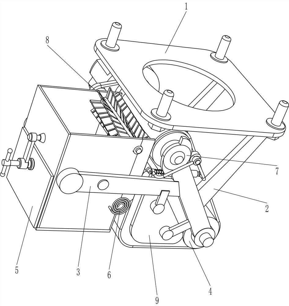
[0053] A magnetic suction type iron debris collector for engineering vehicle wheel protection, such as figure 1 As shown, it includes a mounting plate 1, a bracket 2, a horizontal plate 3, a conveying mechanism 4, a collecting mechanism 5 and a discharge mechanism 6. The bottom of the right side of the mounting plate 1 is connected to the front and rear sides of the bracket 2, and the left part of the bracket 2 is connected to There is a horizontal plate 3, a conveying mechanism 4 is connected between the mounting plate 1 and the support 2, a collecting mechanism 5 is connected between the horizontal plates 3, and a discharge mechanism 6 is connected on the collecting mechanism 5.
[0054] When people need to use the engineering vehicle, the mounting plate 1 is installed on the front part of the front tire of the engineering vehicle, and then the conveying mechanism 4 is started, so that the parts of the collecting mechanism 5 collect the iron objects, and at the same time, the...
Embodiment 2
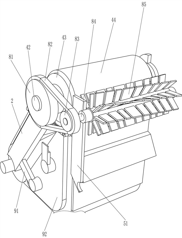
[0056] On the basis of Example 1, such as figure 2 As shown, the conveying mechanism 4 includes a deceleration motor 41, a rotating shaft 42, a roller 43, a conveyor belt 44 and a strong magnet 45, a deceleration motor 41 is connected to the rear left side of the bottom of the mounting plate 1, and a deceleration motor 41 is connected to the left and right sides of the bracket 2. Rotating shaft 42, the rear portion of the rotating shaft 42 on the left side is connected with the output shaft of the reduction motor 41, and the rotating shaft 42 is connected with a drum 43, and a conveyor belt 44 is connected between the drums 43, and a strong magnet 45 is connected between the lower sides of the support 2, and the strong magnet 45 is located within the conveyor belt 44 .
[0057] After the mounting plate 1 is installed on the front part of the front tire of the engineering vehicle, the reduction motor 41 is started, and the output shaft of the reduction motor 41 rotates to driv...
Embodiment 3
[0061] On the basis of Example 2, such as Figure 2-4 As shown, the unloading mechanism 6 includes a rotating rod 61, a mainspring 62 and a scraper 63. The lower right side of the placement frame 51 is rotatably connected with a rotating rod 61. The rotating rod 61 is connected with a scraper 63. The front side of the rotating rod 61 is A clockwork 62 is connected between the placement frame 51 , and the clockwork 62 is sleeved on the rotating rod 61 .
[0062] When the iron filings moved downwards to contact the scraper 63, the iron filings on the conveyor belt 44 would be scraped off by the scraper 63, and then fall into the collection box 52. At the same time, under the action of the spring 62, the scraper 63 Adhere to the conveyor belt 44.
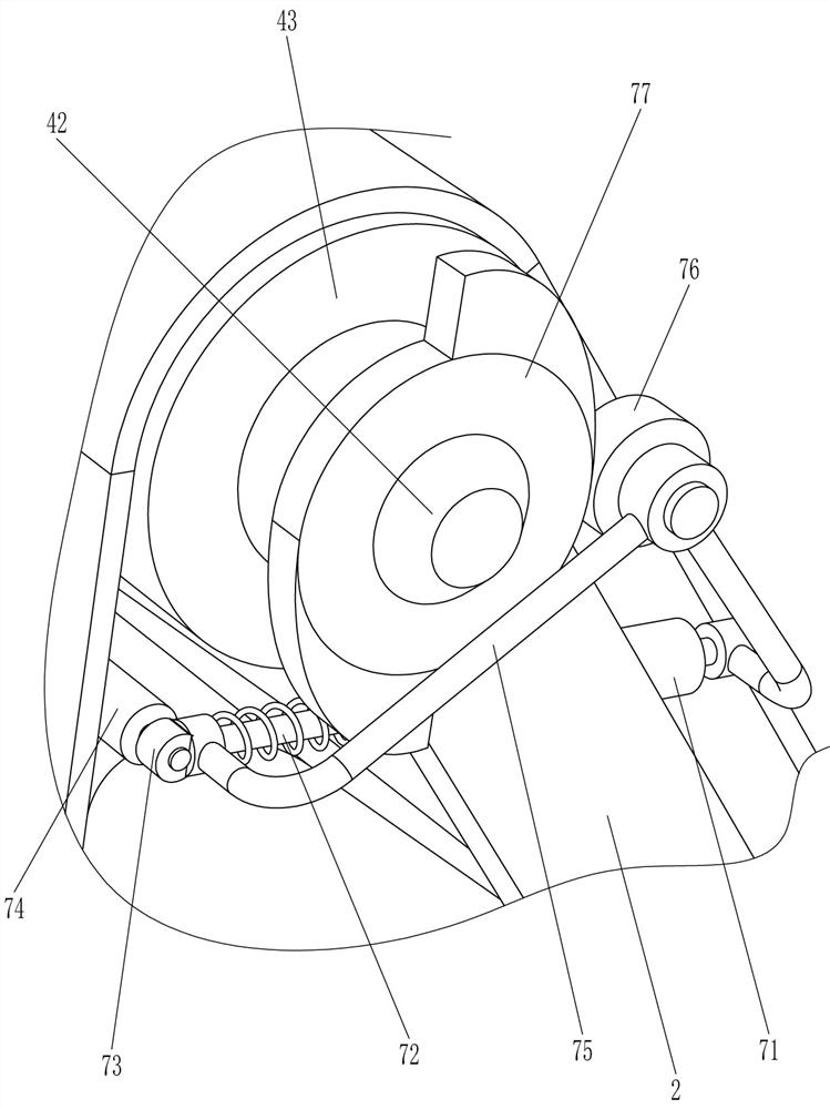
[0063] Also include impact mechanism 7, impact mechanism 7 includes guide sleeve 71, guide rod 72, mounting seat 73, strip roller 74, connecting frame 75, contact wheel 76 and cam 77, support 2 tops are all connected with guide sleeve...
PUM
 Abstract
Description
Claims
Application Information
 - R&D
- Intellectual Property
- Life Sciences
- Materials
- Tech Scout
- Unparalleled Data Quality
- Higher Quality Content
- 60% Fewer Hallucinations
Browse by: Latest US Patents, China's latest patents, Technical Efficacy Thesaurus, Application Domain, Technology Topic, Popular Technical Reports.
© 2025 PatSnap. All rights reserved.Legal|Privacy policy|Modern Slavery Act Transparency Statement|Sitemap|About US| Contact US: help@patsnap.com