
Locking mechanism, battery pack and vehicle

A locking mechanism and battery pack technology, applied in electric vehicles, vehicle energy storage, vehicle components, etc., can solve problems such as poor structural reliability and complex structure of the locking mechanism, achieve convenient installation and removal of batteries, and increase the complexity of operating mechanisms The effect of high speed and convenient operation

Inactive Publication Date: 2021-01-29
ZHEJIANG JIZHI NEW ENERGY AUTOMOBILE TECH CO LTD +1
View PDF6 Cites 0 Cited by
  • Summary
  • Abstract
  • Description
  • Claims
  • Application Information

AI Technical Summary

Problems solved by technology

[0005] The present invention aims to solve the technical problems of complex structure and poor structural reliability of the locking mechanism

Method used


Image

  • Locking mechanism, battery pack and vehicle
  • Locking mechanism, battery pack and vehicle
  • Locking mechanism, battery pack and vehicle

Examples


Embodiment 1

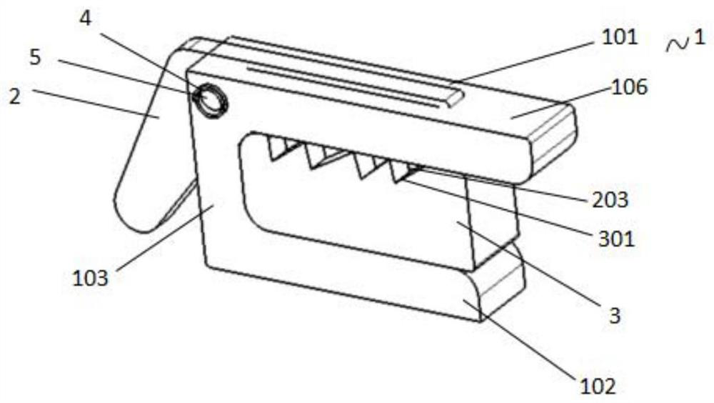
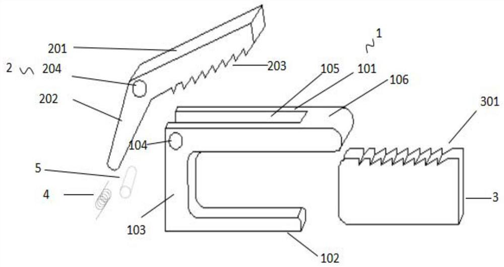
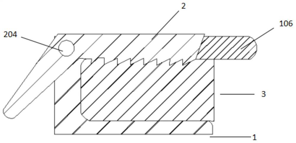
[0034] Figure 1-3 It is an illustration of a preferred embodiment of the present invention, and the following will mainly describe the application of new energy vehicles. It can be understood that these descriptions will also be applicable to other vehicles. figure 1 is a structural schematic diagram of a locking mechanism according to an embodiment of the present invention. In practical applications, the battery pack is fixed on the new energy vehicle through the locking mechanism. The battery pack is generally installed on the chassis of the new energy vehicle. It can be understood that it can also be installed in other positions of other vehicles, such as the cockpit, trunk, etc. .

[0035] From figure 1 It can be seen that the locking mechanism mainly includes a lock base 1, a lock buckle 2, and a lock tongue 3. The lock base 1 is used to support the lock tongue 3. Generally, the lock base 1 is fixedly connected to the chassis of the car, and the lock tongue 3 is fixedl...

Embodiment 2

[0045] refer to Figure 1-3 and combine Figure 4-6 , the present invention also provides another embodiment, the main difference between this embodiment and the embodiment lies in the engaging structure of the locking tongue 3 and the locking buckle 2, and the limiting plate 107 is set on the locking mechanism , for the sake of simplicity, so the content of the same part as in Embodiment 1 will not be repeated, the locking mechanism includes a lock 2 and a lock tongue 3, and the lock 2 and the lock tongue 3 are engaged and connected, as Figure 4 As shown, the top of the lock tongue 3 is a first rectangular tooth pattern 302, and the lock buckle 2 is provided with a second rectangular tooth pattern 205 matched with the first rectangular tooth pattern 302. This kind of rectangular tooth pattern is convenient for unlocking the locking structure. At the same time, the contact area between the lock 2 and the lock tongue 3 is increased, so that under the action of the rotation fo...


PUM


Abstract

The invention relates to the field of new energy vehicles and related technologies thereof, and discloses a locking mechanism which comprises a lock seat, a lock catch, a spring bolt and an elastic piece, the lock catch is arranged on the lock seat and movably connected with the lock seat, the spring bolt is arranged in the lock seat, the spring bolt is connected with the lock catch in an engagedmode, and the elastic piece is arranged in the lock seat. One end of the elastic piece is connected with the lock seat, the other end of the elastic piece is connected with the lock catch, the elasticpiece is used for pressing the lock catch and the spring bolt, and the locking mechanism has the advantages of being simple in structure, convenient to disassemble and high in structural reliability.

Description

technical field [0001] The invention relates to new energy vehicles and related technical fields, in particular to a locking mechanism, a battery pack and a vehicle. Background technique [0002] With the increasingly serious situation of global warming and energy shortage, the research on new energy vehicles at home and abroad has become more urgent. [0003] New energy vehicles have the advantages of low noise, no pollution, and safer and more stable driving. However, one of the main factors affecting the development of new energy vehicles is the problems related to the power battery of new energy vehicles. Generally, the power battery is installed on the chassis of the car. There are fixed and replaceable installation methods. The fixed type is generally fastened to the lower vehicle body by bolts. When charging, the on-board charger is used to supplement power. Since the fixed battery cannot be removed from the vehicle body, this power supplement method Time-consuming a...

Claims


Application Information

Patent Timeline
Patent Type & Authority Applications(China)
IPC IPC(8): B60L53/80B60K1/04H01M50/249H01M50/264
CPCB60K1/04B60K2001/0455B60L53/80Y02T10/70Y02T10/7072
Inventor 王平王明富
Owner ZHEJIANG JIZHI NEW ENERGY AUTOMOBILE TECH CO LTD
Learn More