Annular adjustable positioning tool

A positioning tool and ring technology, applied in positioning devices, manufacturing tools, metal processing equipment, etc., can solve the problems of scrap parts, inaccuracy, and difficulty in alignment, and reduce downtime.

Inactive Publication Date: 2021-01-29
SHENYANG FORTUNE PRECISION EQUIP CO LTD
View PDF0 Cites 1 Cited by
  • Summary
  • Abstract
  • Description
  • Claims
  • Application Information

AI Technical Summary

Problems solved by technology

[0002] In the field of IC equipment manufacturing, there are many types of thin-walled ring parts, which are mostly circular parts with large diameters. When processing such parts, the clamping method is often more important. First, ensure that the parts do not deform. Secondly, when circular parts involve angular positioning, alignment is very difficult and imprecise, and large errors are likely to occur, resulting in the scrapping of parts

Method used


Image

  • Annular adjustable positioning tool
  • Annular adjustable positioning tool
  • Annular adjustable positioning tool

Examples


Embodiment Construction

[0013] Attached below Figure 1-3 The present invention is described in detail.

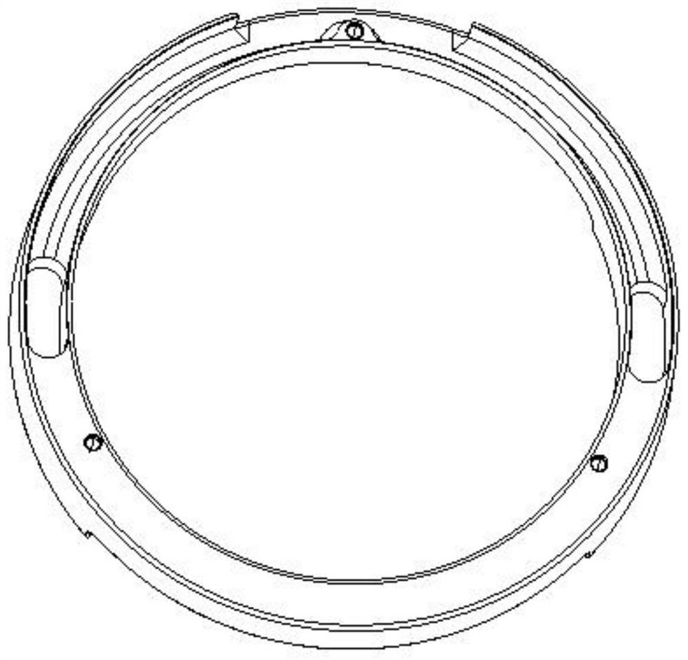
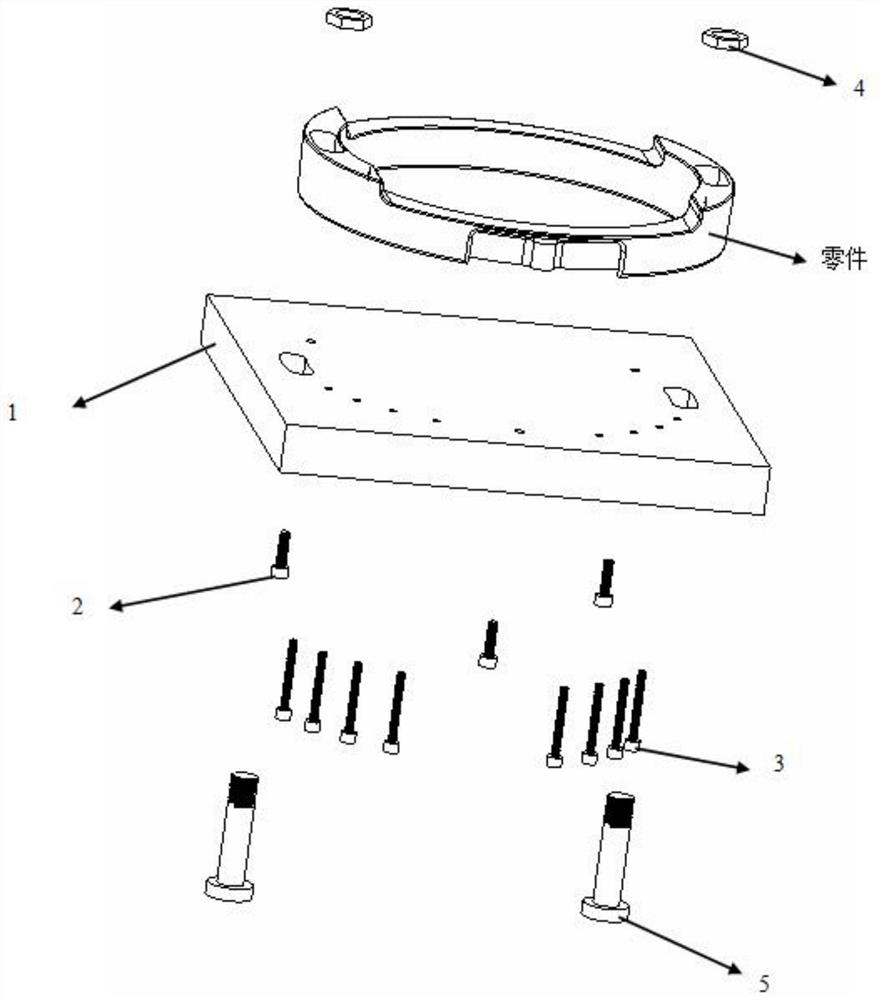
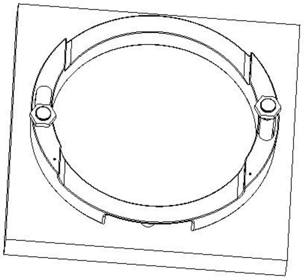
[0014] An annular adjustable positioning tool, including a bottom plate 1, two arc-shaped grooves are arranged on the bottom plate 1, and an adjustable positioning pin 5 is installed in the arc-shaped groove, and the adjustable positioning pin 5 penetrates the part and connects with the nut 4 Screw connection, fix the parts on the bottom plate 1, the positioning pins in the two arc-shaped grooves can adjust different positions according to the parts, and are suitable for parts of different shapes; there are multiple threaded holes on the bottom plate 1, screwed into the threaded holes The reverse locking screw 2 and the adjustable support screw 3; the reverse locking screw 2 is threadedly connected with the part, and the adjustable support screw 3 is in contact with the part to support the thin-walled part and avoid chattering of the knife.


PUM


Abstract

The invention relates to an annular adjustable positioning tool applied to the field of IC equipment manufacturing. The annular adjustable positioning tool comprises a bottom plate. Two arc-shaped grooves are formed in the bottom plate, reverse locking screws are arranged in the arc-shaped groove in a penetrating manner, and the reverse locking screws penetrating a part is in spiral connection toa nut to fix the part to the bottom plate. Positioning pins in the two arc-shaped grooves can be adjusted in different positions according to the part, so that the tool is suitable for parts of different shapes; a plurality of threaded holes are formed in the bottom plate, and adjustable supporting screws can be screwed into the threaded holes; and the adjustable supporting screws abut against thepart, a thin-walled part is supported, and tool vibration is avoided. The positioning pins in the arc-shaped grooves in two sides are used for positioning, a reverse adjustable bolt supports a thin-walled part of the part, and the part is then locked by the adjustable supporting screws, so that the problem that the thin-walled annular part which is hard to clamp is easy to deform is solved.

Description

technical field [0001] The invention is a ring-shaped adjustable positioning tool, which is applied in the field of IC equipment manufacturing. It locates through the positioning pins in the arc grooves on both sides, and the reverse adjustable bolt supports the thin-walled part of the part, and then locks the part through the reverse locking screw. , which solves the problem of difficult clamping and easy deformation of thin-walled ring parts. Background technique [0002] In the field of IC equipment manufacturing, there are many types of thin-walled ring parts, which are mostly circular parts with large diameters. When processing such parts, the clamping method is often more important. First, ensure that the parts do not deform. Second, when circular parts involve angular positioning, alignment is very difficult and imprecise, and large errors are likely to occur, resulting in scrapped parts. Contents of the invention [0003] In view of the above problems, the object ...

Claims


Application Information

Patent Timeline
Patent Type & Authority Applications(China)
IPC IPC(8): B23Q3/00
CPCB23Q3/00
Inventor 丛雪
Owner SHENYANG FORTUNE PRECISION EQUIP CO LTD
Why Eureka
Try Eureka