Heat treatment robot clamping device based on 3D laser scanning

A laser scanning, laser scanner technology, applied in the direction of chucks, manipulators, manufacturing tools, etc., to achieve the effect of compatible clamping

Pending Publication Date: 2020-09-25
JARI AUTOMATION CO LTD CHINA
View PDF0 Cites 1 Cited by
  • Summary
  • Abstract
  • Description
  • Claims
  • Application Information

AI Technical Summary

Problems solved by technology

[0003] For general factories, the introduction of a heat treatment line is bound to handle different types of workpieces, which also poses a challenge for the compatibility of automated production lines

Method used


Image

  • Heat treatment robot clamping device based on 3D laser scanning
  • Heat treatment robot clamping device based on 3D laser scanning
  • Heat treatment robot clamping device based on 3D laser scanning

Examples


Embodiment Construction

[0016] The present invention will be further introduced below in conjunction with the accompanying drawings and specific embodiments.

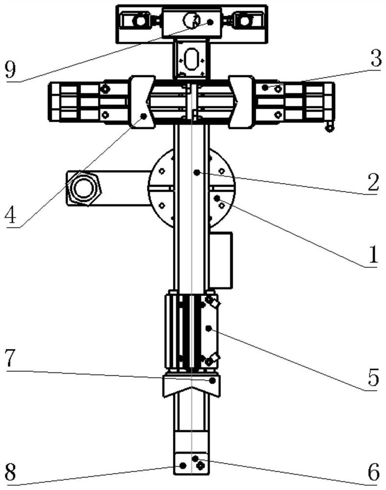
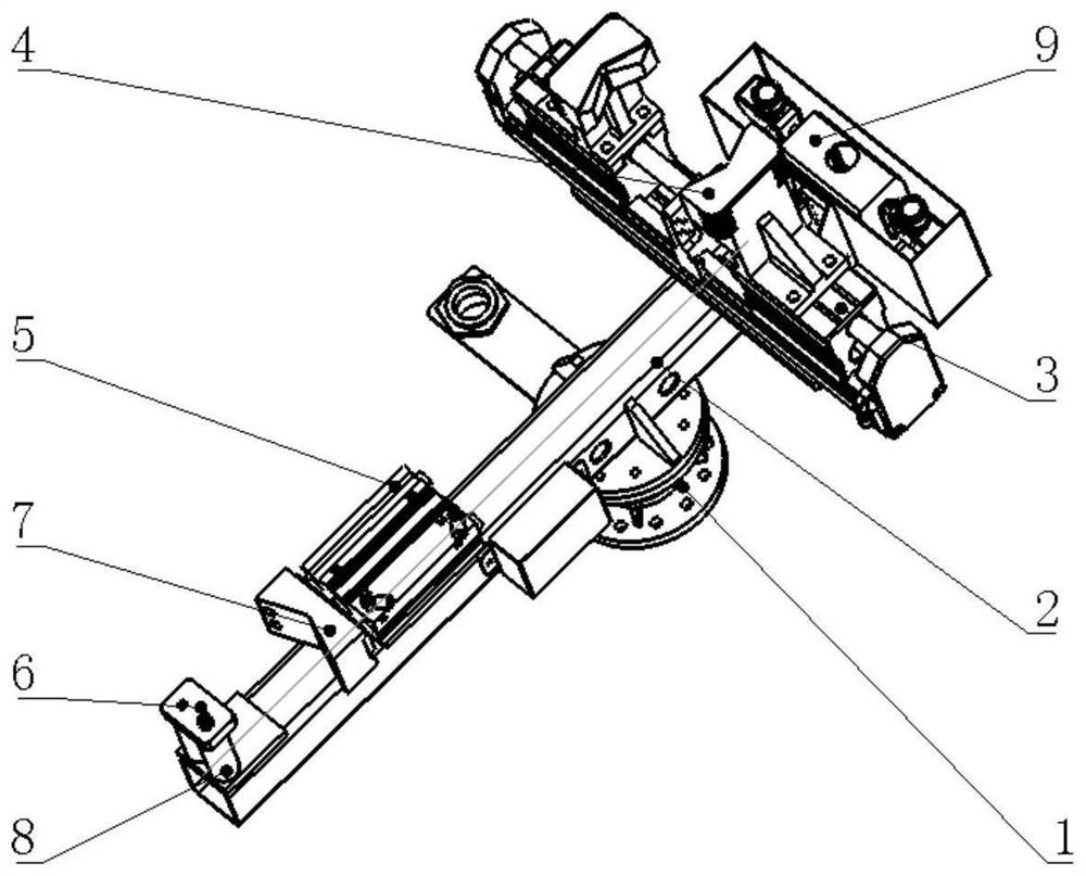
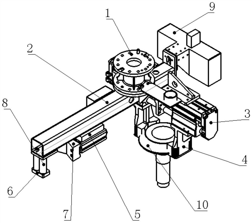
[0017] A heat treatment robot clamping device based on 3D laser scanning of the present invention includes a robot mounting flange plate 1, a mounting base 2, parallel air claws 3, a clamping block 4, a cylinder 5, a connecting plate 8, and a V-shaped positioning block 7 , blocking block 6, 3D laser scanner 9, workpiece 10;

[0018] The robot installation flange plate 1 is used to be fixed at the end of the six-axis robot; the installation base 2 is fixedly connected with the robot installation flange plate 1; the installation base 2 is fixed with a cylinder 5, and the cylinder 5 push rod is connected to the V-shaped The positioning block 7 is connected; at the position facing the V-shaped positioning block 7, a connecting plate 8 is fixed on the installation base 2, and the blocking block 6 and the connecting plate 8 are fixedly connected by ...


PUM


Abstract

The invention discloses a heat treatment robot clamping device based on 3D laser scanning. The heat treatment robot clamping device comprises a robot installing flange plate, an installing base body,a parallel air claw, clamping blocks, an air cylinder, a connecting plate, a locating block, a stop block, a 3D laser scanner and a workpiece. The installing base body is fixedly connected with the robot installing flange plate. A pushing rod of the air cylinder is connected with the locating block. The connecting plate is fixed onto the installing base body. The stop block is fixedly connected with the connecting plate. The air cylinder pushes the locating block to cooperate with the stop block to complete clamping and carrying of the workpiece. The 3D laser scanner is fixed to the installingbase body and used for scanning the workpiece and recognizing position information of stations. The parallel air claw is fixed to the installing base body. Two clamping blocks are symmetrically arranged on the parallel air claw and used for clamping the workpiece. The clamped workpiece is fed to heat treatment equipment. The device improves compatibility of an automatic production line.

Description

technical field [0001] The invention belongs to the field of automatic heat treatment equipment, in particular to a heat treatment robot clamping device based on 3D laser scanning. Background technique [0002] For the heat treatment production line of large workpieces, it is difficult for humans to carry the heat-treated workpieces off-line for a long time, which makes it an inevitable trend for automation to replace manual production. With the advancement of laser measurement technology and the popularization of this type of measurement technology in the market, the detection based on 3D laser is very mature. The key technology of laser scanning measurement, so as to realize the positioning of the spatial position information of the workpiece and the grasping of the workpiece, and complete the off-line work of large workpieces. [0003] For general factories, the introduction of a heat treatment line is bound to handle different types of workpieces, which also poses a cha...

Claims


Application Information

Patent Timeline
Patent Type & Authority Applications(China)
IPC IPC(8): B25J15/02B25J15/08
CPCB25J15/0253B25J15/08
Inventor 韩禄刘志成李志新陆宗学张彬陈修材鲁超奇冯保祖卢中志崔世义
Owner JARI AUTOMATION CO LTD CHINA
Why Eureka
Try Eureka