Pipe winding device for condenser coil pipe

A condenser coil and tube winding technology, applied to heat exchange equipment, etc., can solve the problems of reducing the efficiency of coil winding, complex structure of the tube winding machine, and increasing labor costs, so as to improve efficiency, novel design, and increase labor costs Effect

Inactive Publication Date: 2021-01-29
滁州众科电器有限公司
View PDF0 Cites 0 Cited by
  • Summary
  • Abstract
  • Description
  • Claims
  • Application Information

AI Technical Summary

Problems solved by technology

[0003] A coil winding device for a condenser proposed by the present invention solves the problem that the existing coil winding machine has a complex structure and is inconvenient to operate, and can only wind condensers of the same size. It is time-consuming and labor-intensive to carry out cooperative operations, which increases labor costs and reduces the efficiency of winding pipes

Method used


Image

  • Pipe winding device for condenser coil pipe
  • Pipe winding device for condenser coil pipe
  • Pipe winding device for condenser coil pipe

Examples


Embodiment Construction

[0020] The following will clearly and completely describe the technical solutions in the embodiments of the present invention with reference to the accompanying drawings in the embodiments of the present invention. Obviously, the described embodiments are only some, not all, embodiments of the present invention.

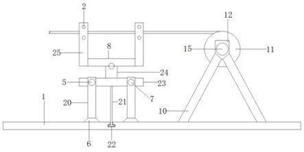
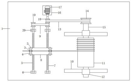
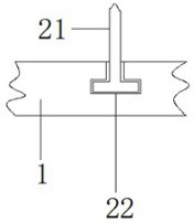
[0021] refer to Figure 1-3 A coil winding device for a condenser coil, comprising a base 1, four trapezoidal blocks 6 are fixedly connected to the bottom of the base 1, and pillars 20 are fixedly connected to the top of the trapezoidal block 6, two pillars 20 on the front and two on the back A moving mechanism is arranged between the two pillars, a positioning mechanism is arranged on the top of the moving mechanism, a winding mechanism is arranged on the right side of the moving mechanism, a driving mechanism is arranged on the back side of the moving mechanism, and a transmission mechanism is arranged between the driving mechanism and the moving mechanism. .

[0...


PUM


Abstract

The invention discloses a pipe winding device for a condenser coil pipe, relates to the technical field of coil pipe winding, aims at solving the problems that an existing pipe winding machine is complex in structure and inconvenient to operate, only condensers of the same size can be wound, meanwhile, due to the fact that manual matched operation is needed, time and labor are wasted, the labor cost is increased, and the pipe winding efficiency is reduced, and discloses the following scheme: the pipe winding device for the condenser coil pipe comprises a base, wherein four trapezoidal blocks are fixedly connected to the bottom of the base; and supporting columns are fixedly connected to the tops of the trapezoidal blocks. The pipe winding device for the condenser coil pipe is novel in design and simple to operate; through synchronous rotation of a first threaded rod and a second threaded rod, a movable block can more stably and longitudinally move, then a second rotating roller can better wind a pipe, meanwhile, due to arrangement for four locating wheels, a straight pipe can be more stably wound in the moving process, moreover, the second rotating rollers of different sizes can bereplaced, different requirements are met, and the pipe winding efficiency is increased.

Description

technical field [0001] The invention relates to the technical field of coil winding, in particular to a coil winding device for a condenser coil. Background technique [0002] The existing tube winding machines can only wind condensers of the same size, and different tube winding machines need to be replaced for different sizes of condensers, which greatly increases the production cost. Although some tube winding machines can achieve different The winding of the freezer body of the same size, but the structure is complicated, and it is very inconvenient to operate. At the same time, because manual operation is required, it is time-consuming and laborious, which increases labor costs and reduces the efficiency of winding pipes. Therefore, a condensation The pipe winding device of the device coil. Contents of the invention [0003] A coil winding device for a condenser proposed by the present invention solves the problem that the existing coil winding machine has a complex ...

Claims


Application Information

Patent Timeline
Patent Type & Authority Applications(China)
IPC IPC(8): B21D53/06B21D11/06
CPCB21D11/06B21D53/06
Inventor 王志远
Owner 滁州众科电器有限公司
Why Eureka
Try Eureka