Angle-adjustable stomatoscope

An adjustable technique for oral mirrors, applied in oral mirrors, endoscopes, medical science, etc., can solve the problems of not being able to cooperate with doctors, increase the difficulty of observation, and small observation field of view, and achieve novel structure, convenient operation, and increased observation range effect

Active Publication Date: 2021-01-29
广州维帝医疗技术有限公司
View PDF4 Cites 2 Cited by
  • Summary
  • Abstract
  • Description
  • Claims
  • Application Information

AI Technical Summary

Problems solved by technology

The existing dental mirrors have a relatively simple structure and a small observation field of view. When a larger area needs to be observed, the handle needs to be turned, which increases the difficulty of observation and cannot cooperate with doctors to make a good diagnosis

Method used


Image

  • Angle-adjustable stomatoscope
  • Angle-adjustable stomatoscope
  • Angle-adjustable stomatoscope

Examples


Embodiment 1

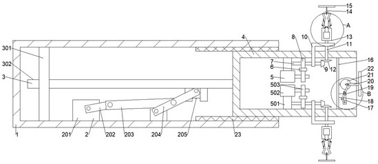
[0024] Example 1: Please refer to Figure 1-4 , an adjustable angle dental mirror, comprising an outer sleeve 1, a first driving mechanism 2, the left side of the outer sleeve 1 is fixedly connected with the first driving mechanism 2, the first driving mechanism 2 is slidably connected with a translation assembly 3, and the translation assembly 3. The inner sleeve 4 is fixedly connected. The left side of the inner sleeve 4 is fixedly connected with the second drive mechanism 5. The middle part of the inner sleeve 4 is slidably connected with the rack 6. The second drive mechanism 5 is rotatably connected with the first rotating shaft 7. The left end of a rotating shaft 7 is fixedly connected with the first gear 8 meshing with the rack 6, the right end of the first rotating shaft 7 is fixedly connected with the first bevel gear 9, and the right end of the first rotating shaft 7 is fixedly connected with the L which is slidingly connected with the side of the inner sleeve 4. Sha...

Embodiment 2

[0033] Embodiment 2: This embodiment is a further improvement of the previous embodiment: the right side of the outer sleeve 1 is fixedly connected with a rubber pad 23 slidingly connected with the inner sleeve 4, so as to reduce the wear and tear caused by the sliding of the inner sleeve 4, Simultaneously avoid the friction of the inner and outer sleeves 1 to make noise.

[0034]The working principle of the present invention is: the first motor 201 provided on the left side of the outer sleeve 1 drives the first rotating rod 202 to rotate, and then drives the first connecting rod 203 to swing, and then drives the rocking bar 204 to swing, and then drives the second slider 205 to swing. The sliding connection with the sliding frame 302 drives the sliding frame 302 to slide left and right, and then drives the inner sleeve 4 to slide left and right, thereby adjusting the length of the entire device; the second motor 502 on the right side of the inner sleeve 4 drives the second ge...


PUM


Abstract

The invention discloses an angle-adjustable stomatoscope, and relates to a stomatoscope device which comprises an outer sleeve, a first driving mechanism is fixedly connected to the left side of the outer sleeve, a translation assembly is slidably connected to the first driving mechanism, an inner sleeve is fixedly connected to the translation assembly, and a second driving mechanism is fixedly connected to the left side of the inner sleeve. The second driving mechanism is rotatably connected with a first rotating shaft, the right end of the first rotating shaft is fixedly connected with an L-shaped plate, a second rotating shaft is rotatably connected above the L-shaped plate, the upper end of the second rotating shaft is fixedly connected with a clamping assembly, the right side of the inner sleeve is fixedly connected with a vertical plate, and the lower part of the right side of the vertical plate is fixedly connected with a third driving mechanism; and the third drive mechanism isrotationally connected with a swing rod, and the upper end of the swing rod is rotationally connected with a swing shaft. The second driving mechanism on the right side of the inner sleeve drives thefirst rotating shaft to rotate, then drives the L-shaped plate to swing and further drives the clamping mechanism and a first mirror surface to swing, so that the side range of the device is observedwithout rotating a handle.

Description

technical field [0001] The invention relates to an oral mirror device, in particular to an adjustable angle oral mirror. Background technique [0002] The oral cavity is the beginning of the digestive tract. The anterior cleft communicates with the outside world, and the posterior pharynx connects with the pharynx. There are teeth, tongue and other organs in the oral cavity. The front wall of the oral cavity is the lips, the side wall is the cheek, the top is the palate, The floor of the oral cavity is composed of mucous membranes and muscles. The oral cavity is divided into the anterolateral oral vestibule and the posteromedial oral cavity by means of the upper and lower dental arches. The gap behind the three molars communicates. Oral disease is a pathological phenomenon that occurs when the oral cavity is damaged by external physical and chemical factors, pathogen invasion, abnormal dentofacial development, and systemic diseases. [0003] The emergence of oral endoscope...

Claims


Application Information

Patent Timeline
IPC IPC(8): A61B1/247A61B1/005
CPCA61B1/0016A61B1/0051A61B1/247
Inventor 杨强
Owner 广州维帝医疗技术有限公司
Why Eureka
Try Eureka