Speed reduction gear assembly

A reduction gear and assembly technology, applied in the direction of gear transmission, belt/chain/gear, transmission parts, etc., can solve the problem of bloated overall structure, and achieve the effect of good deceleration effect, stable force transmission and compact structure

Pending Publication Date: 2021-01-26
浙江源创普贝特尔曼科技有限公司
View PDF0 Cites 1 Cited by
  • Summary
  • Abstract
  • Description
  • Claims
  • Application Information

AI Technical Summary

Problems solved by technology

At present, the reduction mechanism usually adopts a gearbox structure, and the reduction effect is achieved through the combination of multi-stage spur gears and double gears. However, in this reduction gearbox structure, in order to ensure the reduction effect, the number of internal gears is large, making the overall structure relatively bloated. , at the same time, the spur gear tends to generate a lot of noise during the force transmission process

Method used


Image

  • Speed reduction gear assembly
  • Speed reduction gear assembly
  • Speed reduction gear assembly

Examples


Embodiment 1

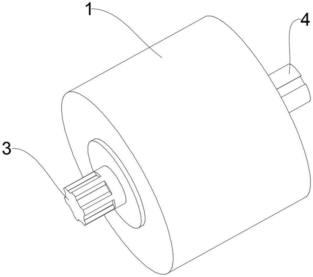
[0029] refer to Figure 1 to Figure 4 As shown in , the reduction gear assembly provided by this embodiment includes:

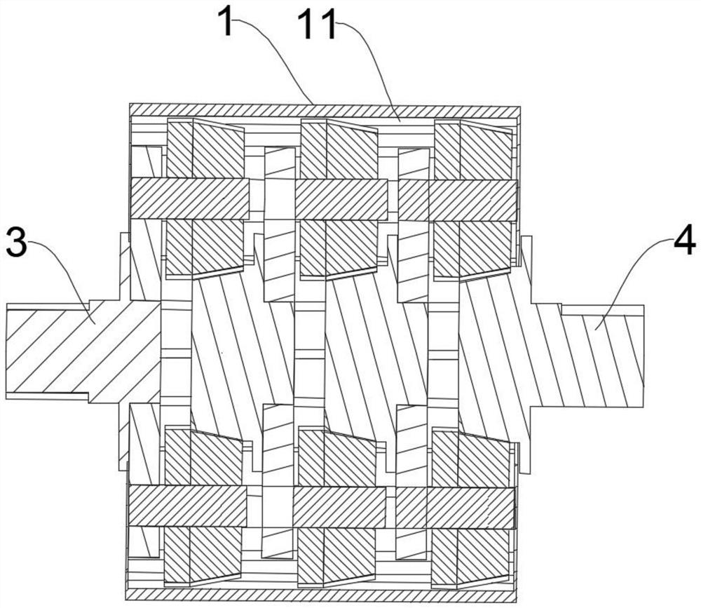
[0030] The outer shell 1 has an internal gear 11 formed on its inner wall;

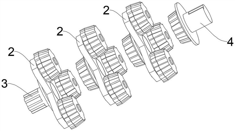
[0031] At least one set of planetary gear assemblies 2, each planetary gear assembly 2 includes a planet carrier 21, a rotatable annular array of at least three planet wheels 22 installed on the front end of the planet carrier 21, each planet wheel 22 is formed by a bevel gear connected front and back 25 and spur gears 26, and each spur gear 26 meshes with the internal gear 11 respectively. Except for the planetary gear assembly 2 located at the rearmost side, each other planetary gear assembly 2 also includes a Sun gear 23, the outer circumference of the sun gear 23 has conical gear teeth matching the shape of the bevel gear 25, and each sun gear 23 meshes with the bevel gears 25 of the three planetary gears 22 on the planet carrier 21 at the rear position ;

[0032] The first fu...

Embodiment 2

[0041] refer to Figure 5 As shown in , the structure of the reduction gear assembly provided by this embodiment is basically the same as that of the first embodiment above, the only difference is that the number of planetary gear assemblies 2 in this embodiment is one set, and there is no sun gear 23, The first functional component 3 and the second functional component 4 are directly connected by transmission through the planetary gear assembly 2 .

Embodiment 3

[0043] refer to Figure 5 As shown in , the structure of the reduction gear assembly provided by this embodiment is basically the same as that of the first embodiment above, the only difference is that the number of planetary gear assemblies 2 is arranged in two groups from back to front.

[0044] Apparently, the number of planetary gear assemblies 2 can be determined according to the requirements of practical applications, and is not limited to one to three sets, and can also be set in more sets, and is not limited thereto.


PUM


Abstract

The invention discloses a speed reduction gear assembly. The speed reduction gear assembly comprises a shell, wherein an inner gear is formed by the inner side wall; at least one planet wheel assemblywherein each planet wheel assembly comprises a planet carrier and at least three planet wheels, each planet wheel is composed of a bevel gear and a straight gear which are connected front and back, the straight gears are meshed with the inner gear, besides the planet wheel assembly located on the rearmost side, the other planet wheel assemblies further comprise sun wheels respectively, and conical gear teeth are arranged on the peripheries of the sun wheels and meshed with the bevel gears on the planet carriers located on the rear side; a first functional member; and second functional member.Furthermore, one of the first functional member and the second functional member serves as an input member for connecting an external motor, and the other serves as an output member for connecting anexternal working device. According to the technical scheme, the overall speed reduction effect can be achieved, force transmission is more stable, the structure is more compact, noise is low, and thespeed reduction effect is better.

Description

technical field [0001] The invention relates to the technical field of gear reduction mechanisms, in particular to a reduction gear assembly. Background technique [0002] The gear reduction mechanism is widely used in various transmission mechanisms, especially in the motor output mechanism. Because of the different application environments, the torque resistance strength of the connecting shaft is different, so the reduction mechanism needs to be used for deceleration to meet various requirements. Application requirements. At present, the reduction mechanism usually adopts a gearbox structure, and the reduction effect is achieved through the combination of multi-stage spur gears and double gears. However, in this reduction gearbox structure, in order to ensure the reduction effect, the number of internal gears is large, which makes the overall structure relatively bloated. , at the same time, spur gears are prone to generate greater noise during force transmission. Cont...

Claims


Application Information

Patent Timeline
IPC IPC(8): F16H57/023F16H57/038F16H57/08F16H1/28
CPCF16H1/2854F16H57/023F16H57/038F16H57/08F16H57/082F16H2057/02086
Inventor 童善方童立浩天
Owner 浙江源创普贝特尔曼科技有限公司
Why Eureka
Try Eureka