Movable isolation ward

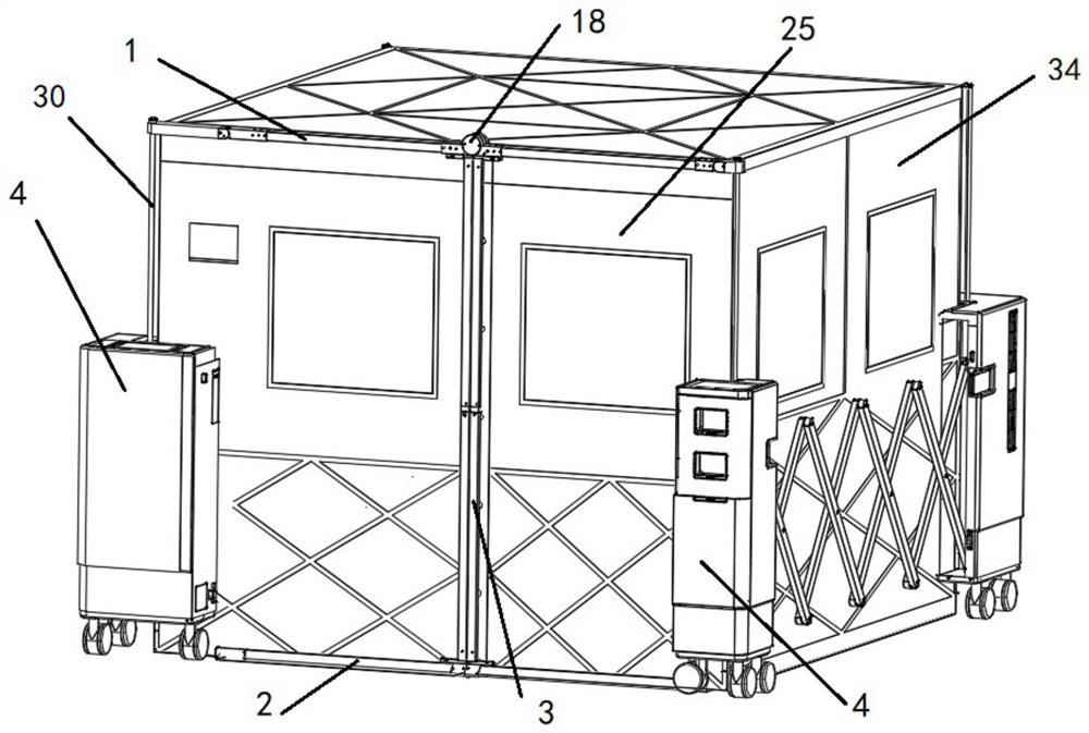
A mobile, ward technology, used in tents/canopies, hospitals, schools, etc., can solve the problems of large use limitations, poor sealing performance of wards, limited effectiveness, etc., to achieve convenient operation of opening and closing doors, improve sealing, functional effect

Pending Publication Date: 2021-01-26
深圳市瑞利医疗科技有限责任公司
View PDF5 Cites 3 Cited by
  • Summary
  • Abstract
  • Description
  • Claims
  • Application Information

AI Technical Summary

Problems solved by technology

However, the effectiveness of these measures is limited, and World Health Organization standards suggest that infected or suspected infected patients should be isolated from other patients
In order to effectively reduce the risk of virus transmission of infectious patients, the application of isolation wards is becoming more and more important. However, most of the traditional isolation wards are fixed, unable to be portable and mobile, and have great limitations in use.
[0003] For this reason, in order to solve this technical defect, there is also a mobile isolation ward in the prior art, which is assembled from a tent cloth body and a tent frame that can be accommodated. When in use, the tent frame is stretched open The tent cloth body forms an isolation cavity inside the tent cloth body. The tent frame generally includes multiple vertical assembly machines distributed in every corner of the tent, but the ward generally requires that each part of the ward has relative airtightness to avoid viruses. Enter and exit from the ward, and the tent door of the mobile isolation ward is in a natural swing state, resulting in extremely poor sealing of the ward, and it is difficult to restrict the flow of air

Method used


Image

  • Movable isolation ward
  • Movable isolation ward
  • Movable isolation ward

Examples


Embodiment Construction

[0050] The technical solutions of the present application will be clearly and completely described below in conjunction with the accompanying drawings. Apparently, the described embodiments are some of the embodiments of the present application, not all of them. Based on the embodiments in this application, all other embodiments obtained by persons of ordinary skill in the art without making creative efforts belong to the scope of protection of this application.

[0051] In the description of this application, it should be noted that the terms "center", "upper", "lower", "left", "right", "vertical", "horizontal", "inner", "outer" etc. The indicated orientation or positional relationship is based on the orientation or positional relationship shown in the drawings, and is only for the convenience of describing the present application and simplifying the description, rather than indicating or implying that the referred device or element must have a specific orientation, use a spec...


PUM


Abstract

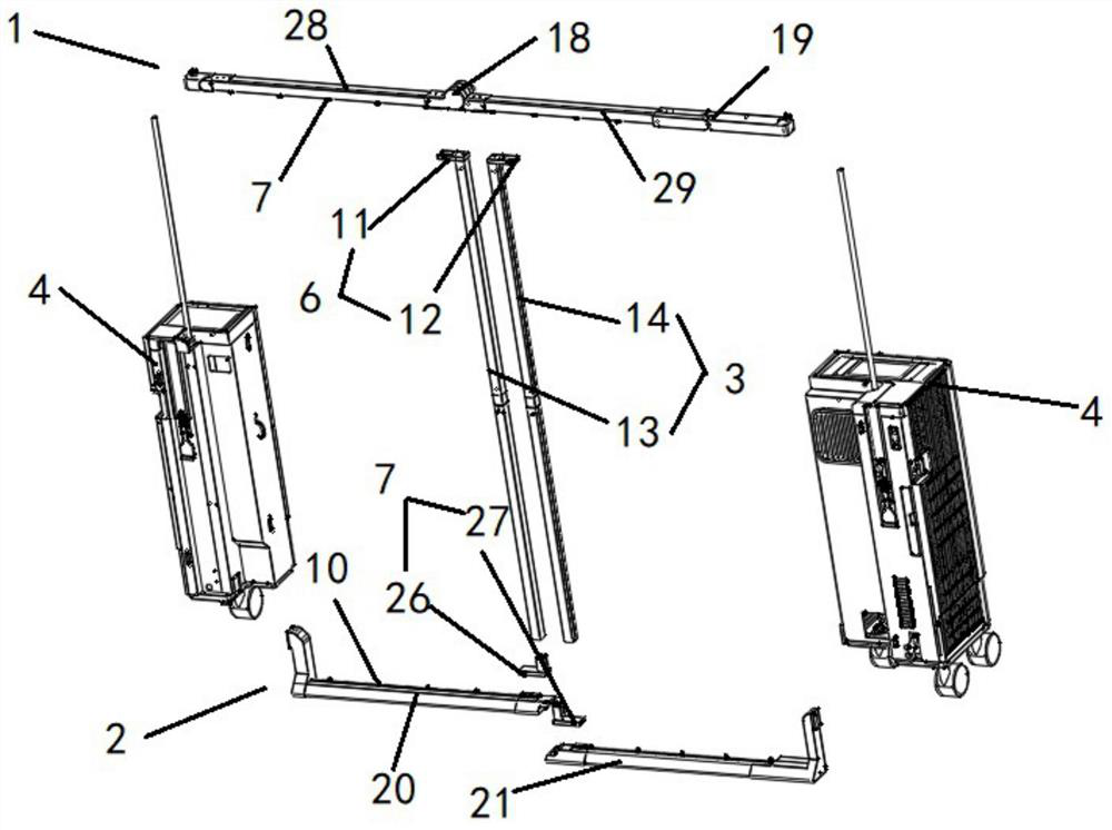
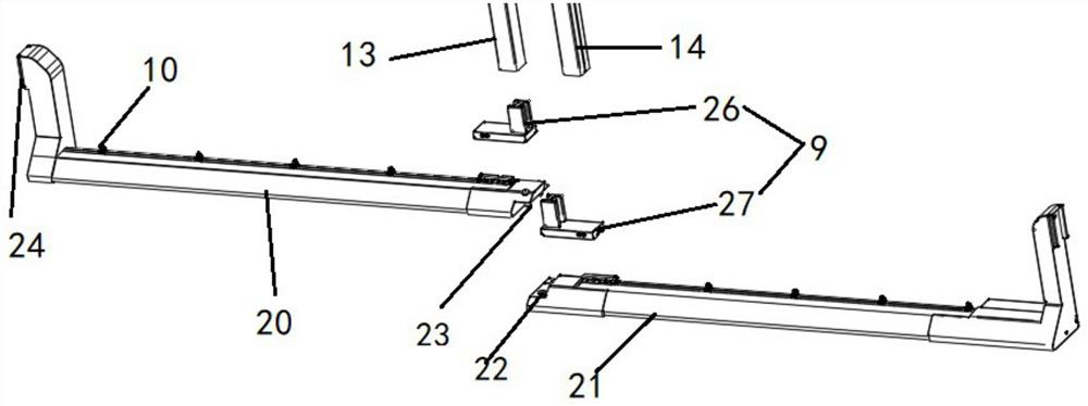
The invention provides a movable isolation ward. The movable isolation ward comprises a door curtain transverse rod, a bottom beam rod, vertical rods, an assembly device and a tent cloth body, the assembly device comprises at least three assembly machines which can be spliced and assembled with one another, each assembly machine is provided with a lifting support rod which is detachably connectedwith the tent cloth body, the assembly device is provided with an air pressure regulator for regulating the air pressure in an isolation chamber, the two ends of the door curtain transverse rod are connected with the lifting rods of the assembly machines on the two sides of a tent door body respectively, the two ends of the bottom beam rod are connected with the bottom ends of the assembly machines on the two sides of the tent door body respectively, a first guide rail is arranged on the bottom surface of the door curtain transverse rod, a first sliding block set and first sliding hooks are slidably arranged on the first guide rail, a second guide rail is arranged on the top face of the bottom beam rod, and a second sliding block set and second sliding hooks are slidably arranged on the second guide rail. According to the movable isolation ward, the technical problems that a tent door body of a movable isolation ward is in a natural swinging state, so that the sealing performance of the ward is extremely poor, and air flowing is difficult to limit are solved.

Description

technical field [0001] The application relates to the field of medical equipment, in particular to a mobile isolation ward. Background technique [0002] Infections are usually spread by a number of different mechanisms, including contact, droplet, and airborne. Current best practices for reducing infection rates often rely on basic hygiene measures, such as regular hand washing, surface disinfection, and equipment disinfection, to prevent infection of other patients. However, the effectiveness of these measures is limited, and World Health Organization standards suggest that infected or suspected infected patients should be isolated from other patients. In order to effectively reduce the risk of virus transmission of infectious patients, the application of isolation wards is becoming more and more important. However, most of the traditional isolation wards are fixed, unable to be portable and mobile, and have great limitations in use. [0003] For this reason, in order to...

Claims


Application Information

Patent Timeline
Patent Type & Authority Applications(China)
IPC IPC(8): E04H3/08E04H15/58E04H15/32E04H15/14
CPCE04H3/08E04H15/14E04H15/32E04H15/58
Inventor 何伟岑振宙黄愉太
Owner 深圳市瑞利医疗科技有限责任公司
Why Eureka
Try Eureka