
Forming assembly for plugging of prefabricated concrete grouting layer as well as component and method

A concrete and prefabricated technology, applied in building construction, construction, building material processing and other directions, can solve the problems of insufficient sleeve grouting fullness, dangerous buildings, hidden dangers of engineering safety, etc., achieve fully qualified construction quality and improve work efficiency. Efficiency, the effect of meeting safety requirements

Active Publication Date: 2021-01-26
山东省建筑科学研究院有限公司 +2
View PDF10 Cites 2 Cited by
  • Summary
  • Abstract
  • Description
  • Claims
  • Application Information

AI Technical Summary

Problems solved by technology

The grout is poured into the joints to form a grouting layer, but in this arrangement, the inventor found that the grout is easily squeezed near the steel bar, thereby blocking the grouting sleeve, resulting in the inability to pour grout into the grouting sleeve , causing a certain safety hazard to the project
[0005] The inventor also found that, using the existing grouting sleeve construction technology, the bottom seams of the prefabricated components are made of soft elastic materials such as rubber and plastic strips, which are easily compressed and deformed under pressure for a long time, causing the top grout to fall back; the prefabricated components The bottom seam is not strictly leaking, causing the top slurry to fall; the air brought in by stirring and the air enclosed during grouting will turn up when standing, causing the top slurry to fall; the warehouse will cause the top slurry to fall; The liquid level may be lower than the height required by the minimum anchorage length 8d of steel bars caused by the fall
Insufficient sleeve grouting fullness brings great safety hazards to the project, and even becomes a dangerous building

Method used


Image

  • Forming assembly for plugging of prefabricated concrete grouting layer as well as component and method
  • Forming assembly for plugging of prefabricated concrete grouting layer as well as component and method
  • Forming assembly for plugging of prefabricated concrete grouting layer as well as component and method

Examples


Embodiment 1

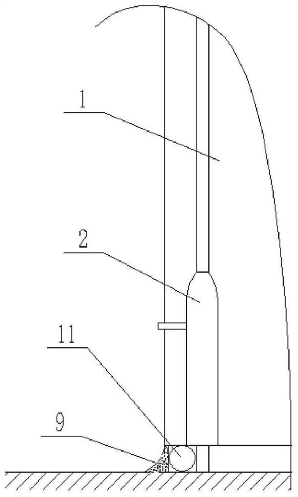
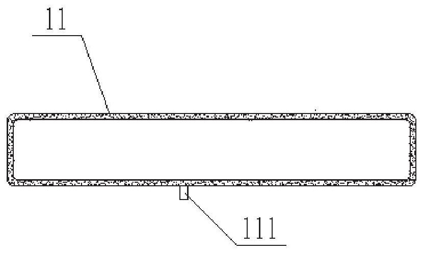
[0032] This embodiment provides a prefabricated concrete grouting layer plugging forming assembly, including a back-shaped or concave-shaped rubber hose surrounding the grouting layer area. The rubber hose can communicate with an external air source to realize inflation and deflation. The rubber hose is set as: In the case of inflation, the grouting layer area is isolated from the outside, and a sealing space is formed outside the hose, which is used to fill the sealing material to form a sealing structure.

[0033] Specifically, an air nozzle 111 is provided on the side wall of the rubber hose 11, and the air nozzle 111 can protrude from the notch. It can be understood that in this solution, the rubber hose adopts an inflatable structure, so that the volume of the rubber hose can be adjusted easily, and when the rubber hose is deflated, it can be easily pulled out from the sealing structure formed by the sealing slurry.

[0034] In this embodiment, the back-shaped rubber hose...

Embodiment 2

[0036] This embodiment provides a plugging method for the assembled concrete grouting layer 8, comprising the following steps:

[0037] In step 1, the wall panel 1 is placed on the upper surface of the floor slab, and the steel bar 3 in the floor slab is inserted into the cylinder 2 in the wall panel 1 .

[0038] In step 2, a gap is reserved between the lower surface of the wall panel 1 and the upper surface of the floor slab to facilitate the pouring of the grouting layer 8; specifically, a spacer is provided between the lower surface of the wall panel 1 and the upper surface of the floor slab to form a gap , The pad and the poured grout in the grout layer 8 form an integral structure.

[0039] Step 3, arrange a rubber hose 11 around the area where the grouting layer 8 is located, and inflate the rubber hose 11 so that the lower opening of the cylinder body 2 is isolated from the external environment.

[0040] Step 4, filling the sealing material in the sealing space outside...

Embodiment 3

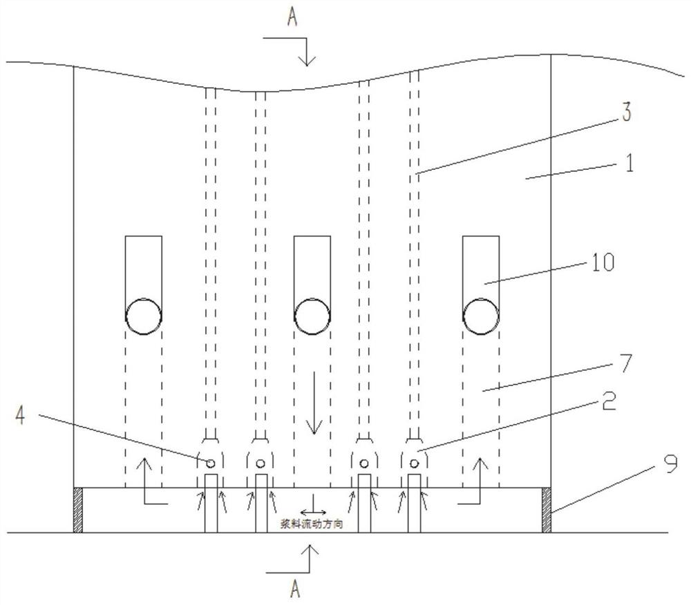
[0044] This embodiment provides a prefabricated concrete component. The wall panel 1 is arranged above the floor, and the sealing structure 9 described in Embodiment 1 is arranged between the wall panel 1 and the floor. The sealing structure 9 encloses a pouring space. The grouting layer 8 formed by pouring in the pouring space is used for bonding the wall panel 1 and the floor slab.

[0045] A grouting pipe 6 is provided in the wallboard 1, and the opening at the lower end of the grouting pipe 6 passes through the lower end surface of the wallboard 1 and communicates with the space where the grouting layer 8 is located; the opening at the upper end of the grouting pipe 6 passes through the side of the wallboard 1, And can communicate with external grouting equipment.

[0046] Specifically, an indicator tube 7 is pre-embedded in the wall panel 1, and the opening at the lower end of the indicator tube 7 passes through the lower end surface of the wall panel 1 and communicates w...


PUM


Abstract

The invention relates to a forming assembly for plugging of a prefabricated concrete grouting layer as well as a component and a method. The forming assembly comprises a concentric-square-shaped or U-shaped rubber pipe surrounding a grouting layer area, wherein the rubber pipe can communicate with an external air source to achieve inflation and deflation, and the rubber pipe is arranged with the functions that under the condition of inflation, the grouting layer area is isolated from the outside, a plugging space is formed on the outer side of the rubber pipe, and the plugging space is used for being filled with sealing slurry so as to form a plugging structure; and an air nozzle is arranged on the side wall of the rubber pipe and can extend out of a notch. According to the forming assembly for plugging of the prefabricated concrete grouting layer as well as the component and the method, pouring of the plugging structure at the grouting layer can be conveniently achieved.

Description

technical field [0001] The invention belongs to the technical field of civil engineering, and in particular relates to a forming assembly, a component and a method for plugging an assembled concrete grouting layer. Background technique [0002] The statements herein merely provide background information related to the present invention and do not necessarily constitute prior art. [0003] There are two ways of grouting connection operation for sleeve grouting, namely pressure type and gravity type. Both of these methods are to set the grouting port and the grouting port on the grouting sleeve. The grout is injected from the grouting port during the construction of the grouting sleeve at present, but the inventor has found that in order to ensure the strength of the grouting sleeve, the grouting sleeve The size of the grouting port is small, and the work efficiency of grouting through the grouting port is low. [0004] At the same time, in the existing scheme, soft elastic ...

Claims


Application Information

Patent Timeline
IPC IPC(8): E04G21/02E04G21/24
CPCE04G21/02E04G21/246
Inventor 宋双阳崔士起孙建东石磊李晓鹏刘文政
Owner 山东省建筑科学研究院有限公司
Learn More