
Reaction kettle, reaction system and reaction method

A reaction system and reactor technology, applied in the chemical industry, can solve problems such as too late condensation, too much solvent volatilization, and product explosion, so as to reduce the possibility of explosion, reduce condensation load, and improve consistency

Pending Publication Date: 2021-01-26
贵州省欣紫鸿药用辅料有限公司
View PDF3 Cites 0 Cited by
  • Summary
  • Abstract
  • Description
  • Claims
  • Application Information

AI Technical Summary

Problems solved by technology

[0007] However, the problem with the use of peripheral condensers is that most of the peripheral condensers are tube-and-tube type. Before or during the reaction detonation, the solvent volatilizes too much, and it is too late to condense, resulting in a reduction in the heat dissipation effect of the condenser. Formation of a liquid seal, resulting in product implosion
[0008] Even under normal reaction conditions, the properties of the products produced by it are not easy to control the consistency

Method used


Image

  • Reaction kettle, reaction system and reaction method
  • Reaction kettle, reaction system and reaction method
  • Reaction kettle, reaction system and reaction method

Examples


Embodiment 1

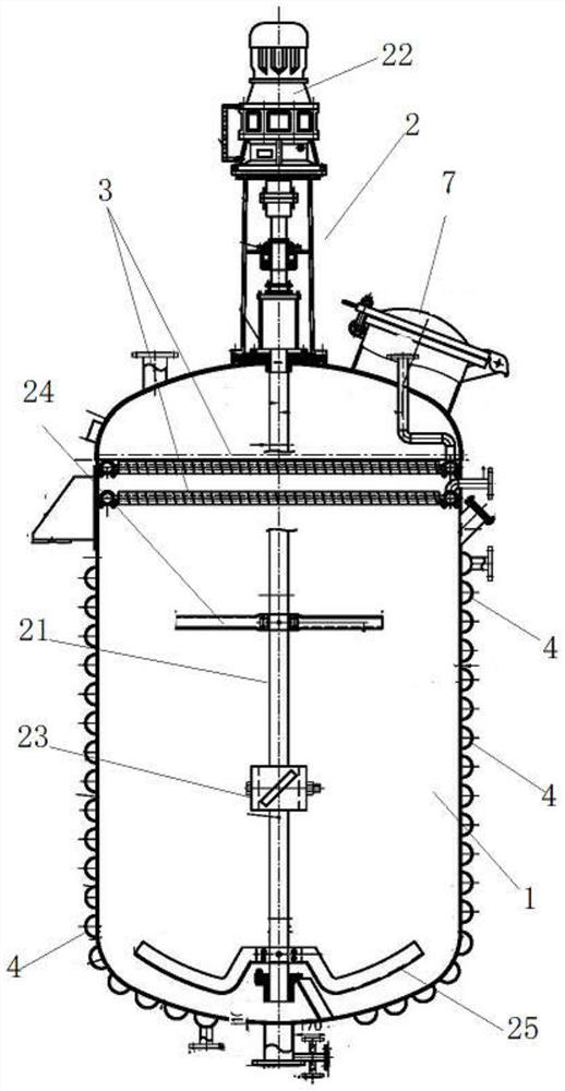
[0042] see Figure 1~5 , a reaction kettle, comprising a kettle body 1 and an agitator 2 extending into the kettle body 1, the upper part of the inner cavity of the kettle body 1 is provided with a cooling layer;

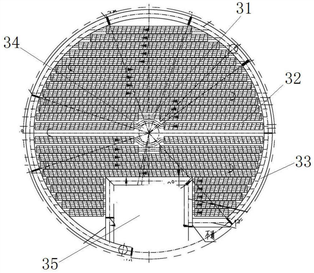
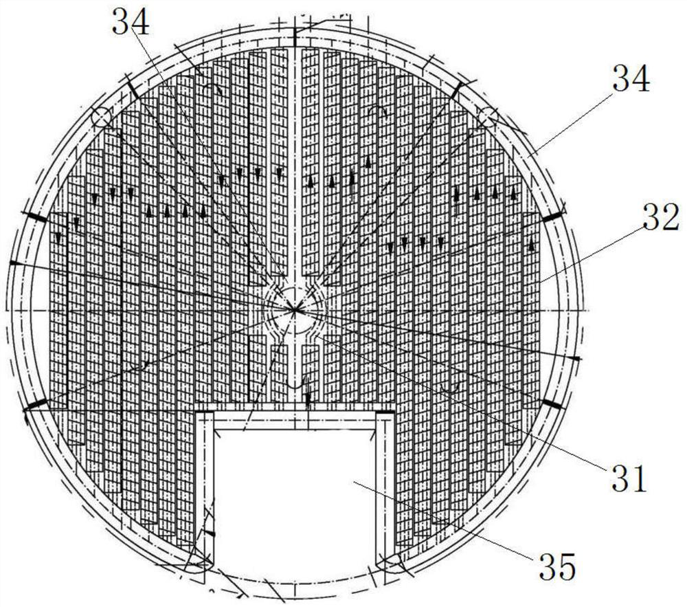
[0043] The cooling layer is at least one fin layer 3;

[0044] The fin layer 3 is composed of a plurality of cooling tubes 31 arranged side by side, and the cooling tubes 31 are provided with fins 32 .

[0045] In practical applications, the fin layer 3 can be 1 layer, 2 layers or 3 layers; the refrigerant, such as supercooled brine, is passed into the cooling pipe 31, and the fins 32 are mainly used to transfer the heat of the solvent vapor and the heat in the cooling pipe 31. The heat of the refrigerant is exchanged. The fins 32 extend along the length direction of the cooling tube 31 .

[0046] As a further improvement, an inert gas supply pipe is provided at the bottom of the still body. During the reaction, nitrogen is supplied through the inert gas supply p...

Embodiment 2

[0064] refer to Figure 6 , a reaction system, comprising a stirred tank as described in embodiment 1 and a cooler externally connected to the reactor, the cooler is a horizontal condenser 6, and the inlet of the horizontal condenser communicates with the reactor , the outlet of the horizontal condenser is connected with a liquid storage tank 5, and a reflux pump is arranged between the liquid storage tank 5 and the reactor; the liquid storage tank or the horizontal condenser or the liquid storage tank and the horizontal condenser There is a vent opening connected to the atmosphere between the devices to release non-condensable gas.

[0065] Through the combination of the external condenser and the fin layer 3, the solvent vapor can be condensed more favorably, and at the same time, the significant change of the solvent content in the system caused by the temperature fluctuation can be reduced, so that the reaction is more stable and controllable.

[0066] Application Test 1 ...


PUM


Abstract

The invention belongs to the field of chemical engineering, and discloses a reaction kettle which comprises a kettle body and a stirrer extending into the kettle body, and a cooling layer is arrangedat the upper part of an inner cavity of the kettle body; the cooling layer is at least one fin layer; and the fin layer is composed of a plurality of cooling pipes side by side, and fins are arrangedon the cooling pipes. According to the reaction kettle, the cooling layer with the fins is additionally arranged, so that a gasified solvent can be repeatedly liquefied in the kettle, the condensationload of an external cooler is reduced, the possibility of implosion of polymerization reaction is reduced, and the consistency of reaction products is improved. Meanwhile, the invention also providesa reaction system and a reaction method.

Description

technical field [0001] The invention relates to the field of chemical industry, in particular to a reaction kettle, a reaction system and a reaction method. Background technique [0002] Application number CN201910452586.8 discloses a hydrothermal reaction kettle with flexible arrangement of fins inside the kettle. The hydrothermal reaction kettle includes a stirring motor, a kettle cover, a flange, a reactor body, a motor stirring rod, a stirring paddle, Fins; the reactor body is provided with a matching kettle cover, and a stirring motor is installed on the kettle cover; the motor stirring rod is sealed and rotated with the kettle cover, the top of the motor stirring rod is connected to the stirring motor, and the lower end is equipped with a stirring paddle; There is at least one inner fin in the reactor; the inner fin includes an annular inner ring, and a plurality of fin plates are fixed on the outer wall of the inner annular ring; the stirring paddle is located in the ...

Claims


Application Information

Patent Timeline
Patent Type & Authority Applications(China)
IPC IPC(8): B01J19/18F28D7/08F28F1/12
CPCB01J19/18B01J19/0053F28D7/082F28F1/12
Inventor 沈惠
Owner 贵州省欣紫鸿药用辅料有限公司
Learn More