
Mixing device for automatic powder batching system

A mixing device and automatic batching technology, which is applied in the direction of solid-solid mixing, mixers, mixing methods, etc., can solve problems that are easy to cause accidents, achieve the effects of avoiding collisions, improving comfort, and reducing extrusion damage

Pending Publication Date: 2021-01-26
CHANGZHOU AOEN MEASURING EQUIP
View PDF0 Cites 0 Cited by
  • Summary
  • Abstract
  • Description
  • Claims
  • Application Information

AI Technical Summary

Problems solved by technology

[0002] With the continuous development of science and technology, the requirements for production automation are getting higher and higher. The original production batching device is far from meeting the current needs of high automation. In order to reduce labor intensity, improve the reliability and safety of production, reduce production costs, and reduce Environmental pollution, improving product quality and economic benefits are major problems that enterprises must face in production. Many automatic powder batching systems are used, and mixing devices are used in the powder automatic batching system to mix different powders for easy processing use in different environments
[0003] When using the existing mixing device for the automatic powder batching system, it is necessary to seal the closing cover and the feeding pipe, but during the closing process, if the external collision or excessive force is applied, it is easy to cause The closing cover is quickly closed on the end face of the feeding pipe, and the nozzle of the feeding pipe is squeezed, which is easy to cause accidents, so the existing mixing device has a certain room for improvement

Method used


Image

  • Mixing device for automatic powder batching system
  • Mixing device for automatic powder batching system
  • Mixing device for automatic powder batching system

Examples


Embodiment approach

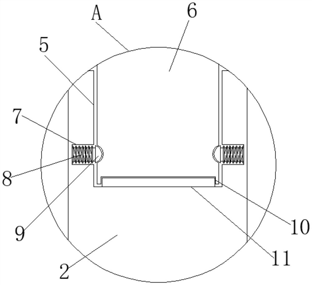
[0021] As an embodiment of the present invention, a mounting block 15 is symmetrically installed on the side surface of the mixing device main body 1, and a rotating column 16 is installed through the inside of the mounting block 15, and a mounting groove 14 is symmetrically opened on the inner wall of the handle 4, and the rotating column 16 The end of the mounting block 15 is limitedly engaged with the mounting groove 14, and one end of the mounting block 15 is provided with a fixing bolt 17 penetrating to the surface of the rotating column 16, and the fixing bolt 17 and the rotating column 16 are extruded and fitted.

[0022] As an embodiment of the present invention, a fixing groove 12 is provided inside the handle 4, and a rubber pad B13 is arranged inside the fixing groove 12, and the thickness of the rubber pad B13 is one centimeter.

[0023] As an embodiment of the present invention, the surface of the limiting head 9 is arc-shaped, and the diameter of the limiting head...


PUM


Abstract

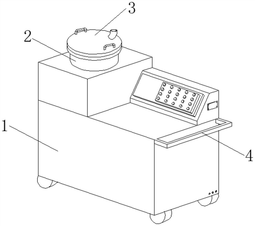
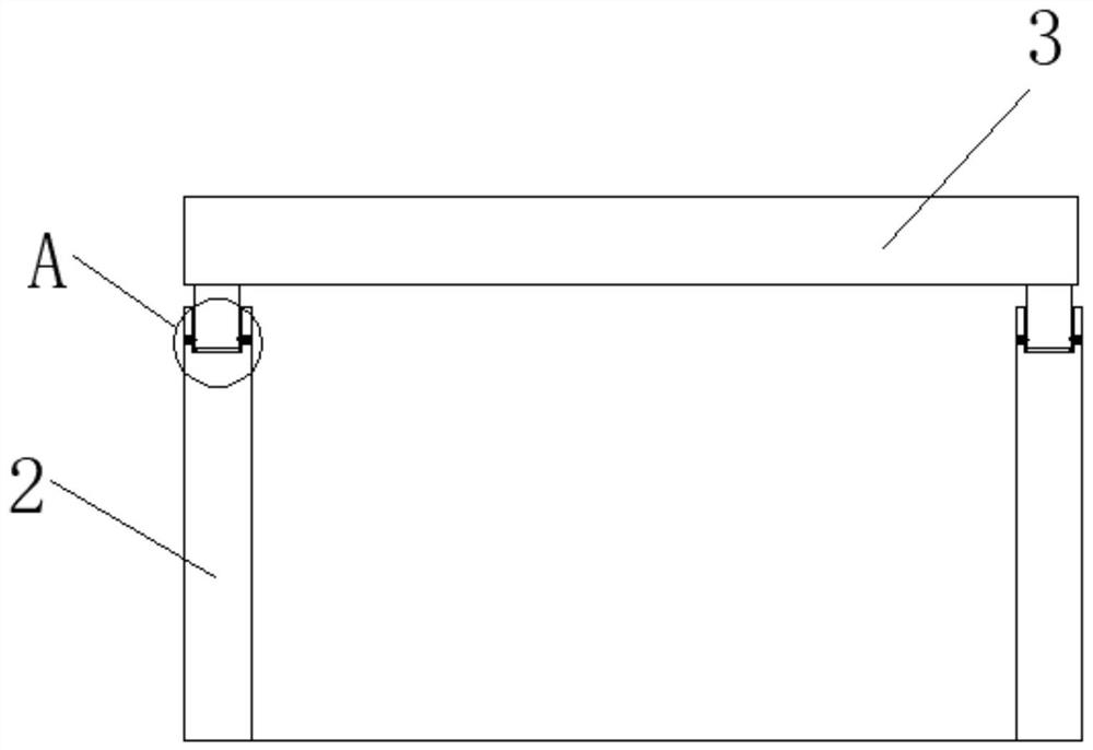
The invention discloses a mixing device for an automatic powder batching system. The mixing device comprises a mixing device main body, a feeding pipe, a closing cover, a handle, a limiting groove, alimiting bulge, a spring groove, a limiting spring, a limiting head, a groove, a rubber pad A, a fixing groove, a rubber pad B, a mounting groove, a mounting block, a rotating column and a fixing bolt, the feeding pipe is mounted at the top of the mixing device main body, the closing cover is rotatably mounted at the top of the feeding pipe, a handle is arranged on the side edge of the mixing device main body, and the limiting groove is formed in the top end surface of the feeding pipe; the purpose of conveniently sealing and covering the closing cover is achieved through the designed limitingbulge and limiting groove, meanwhile, the effect of conveniently and rapidly covering the closing cover for shock absorption is achieved through the designed rubber pad A and limiting spring, and extrusion damage of the closing cover to the feeding pipe is reduced; and meanwhile, the closing cover is not prone to shaking or opening when the closing cover is closed, and powder is not prone to leaking.

Description

technical field [0001] The invention relates to the technical field of an automatic powder batching system, in particular to a mixing device for an automatic powder batching system. Background technique [0002] With the continuous development of science and technology, the requirements for production automation are getting higher and higher. The original production batching device is far from meeting the current needs of high automation. In order to reduce labor intensity, improve the reliability and safety of production, reduce production costs, and reduce Environmental pollution, improving product quality and economic benefits are major problems that enterprises must face in production. Many automatic powder batching systems are used, and mixing devices are used in the powder automatic batching system to mix different powders for easy processing used in different environments. [0003] When using the existing mixing device for the automatic powder batching system, it is ...

Claims


Application Information

Patent Timeline
Patent Type & Authority Applications(China)
IPC IPC(8): B01F3/18B01F15/00
CPCB01F23/60B01F35/45
Inventor 陈香香陈利萍景季平陆伟华谢蕾万会虎
Owner CHANGZHOU AOEN MEASURING EQUIP
Learn More