
Motor and rotor thereof

A technology of rotor and rotor core, applied in the direction of electromechanical devices, electrical components, electric components, etc., can solve the problem of uneven fastening of rotor punching pieces, and achieve the effects of improving heat dissipation efficiency, solving stress concentration, and connecting firmly and reliably

Pending Publication Date: 2021-01-22
QINGDAO CCS ELECTRIC CORP
View PDF24 Cites 0 Cited by
  • Summary
  • Abstract
  • Description
  • Claims
  • Application Information

AI Technical Summary

Problems solved by technology

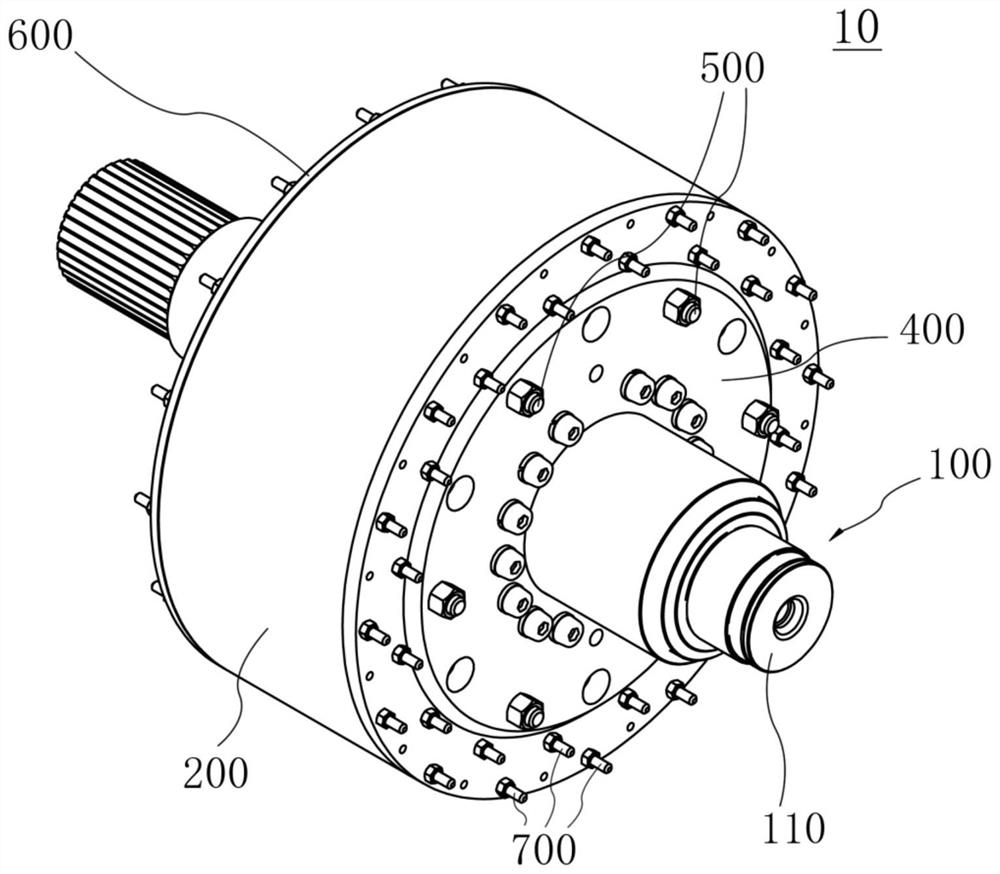
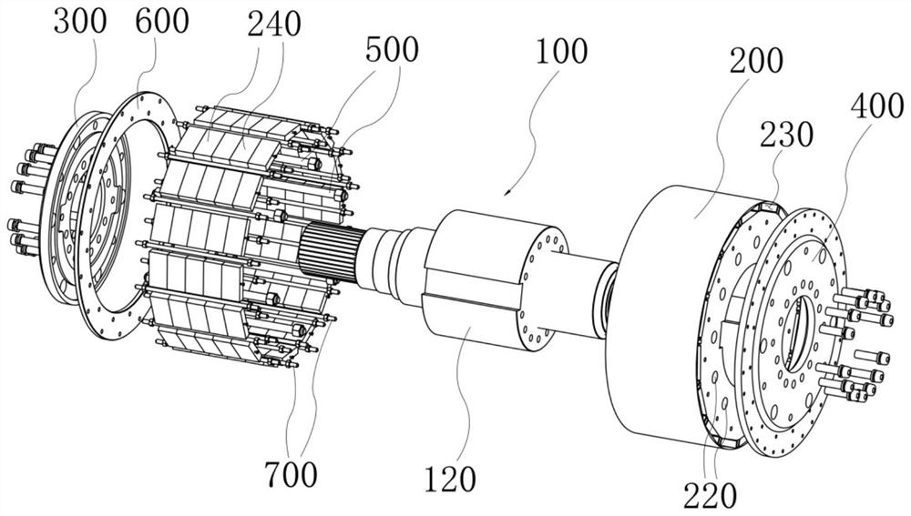
[0005] An object of the present invention is to provide a rotor of a motor to improve the problem of uneven fastening of the rotor sheet in the prior art

Method used


Image

  • Motor and rotor thereof
  • Motor and rotor thereof
  • Motor and rotor thereof

Examples


Embodiment Construction

[0033] The following will clearly and completely describe the technical solutions in the embodiments of the present invention with reference to the accompanying drawings in the embodiments of the present invention. Obviously, the described embodiments are part of the embodiments of the present invention, but not all of them. Based on the implementation manners in the present invention, all other implementation manners obtained by those skilled in the art without creative efforts shall fall within the protection scope of the present invention.

[0034] It should be understood that the terms "first", "second", "third" and "fourth" in the claims, description and drawings of the present invention are used to distinguish different objects, rather than to describe a specific order . The terms "comprising" and "comprising" used in the description and claims of the present invention indicate the presence of described features, integers, steps, operations, elements and / or components, b...


PUM


Abstract

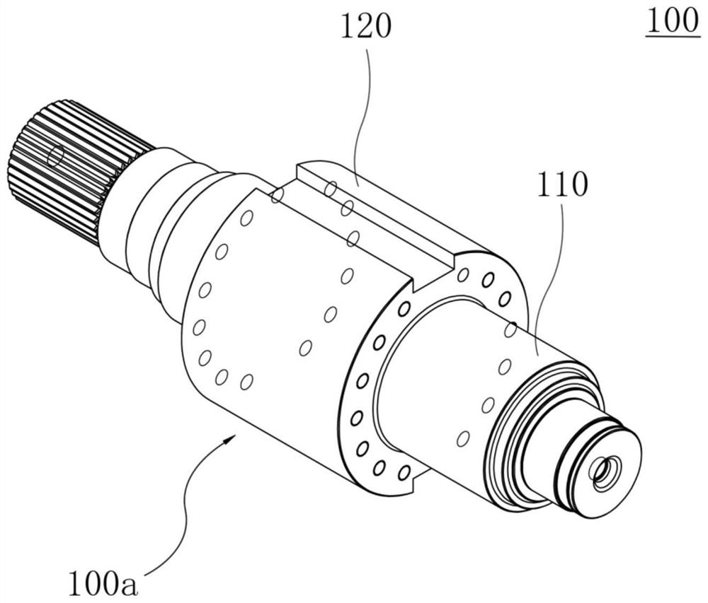
The invention relates to a motor and a rotor thereof. The rotor can comprise: a rotating shaft which comprises a connecting part located at the middle section of the rotating shaft; a rotor iron core,wherein a connection hole is arranged at the central portion of the rotor iron core, and is connected to the connecting part of the rotating shaft; and a front-end pressing plate and a rear-end pressing plate, wherein the front-end pressing plate is connected with the rotating shaft at the first side of the rotor iron core, and the rear-end pressing plate is connected with the rotating shaft at the second side of the rotor iron core, so that the front-end pressing plate and the rear-end pressing plate tightly press the rotor iron core. According to the invention, the rotor of the motor has the beneficial effects that the rotor punching sheet is not easy to deform, and the fastening is uniform; and the rotor disclosed by the invention is high in heat dissipation efficiency and convenient for dynamic balance adjustment.

Description

technical field [0001] The present invention relates generally to the field of electrical machine construction. More specifically, the present invention relates to an electric machine and its rotor. Background technique [0002] A rotating electrical machine (hereinafter referred to as a motor) is a rotating electromagnetic machine that operates on the principle of electromagnetic induction, and is used to realize the mutual conversion of mechanical energy and electrical energy. The principle of motor operation is based on the law of electromagnetic induction and the law of electromagnetic force. When the motor performs energy conversion, it should have two major parts that can perform relative motion: the part that establishes the excitation magnetic field, and the induced part that induces the electromotive force and flows the working current. Of these two components, the stationary one is called the stator, and the rotating one is called the rotor. There is an air gap ...

Claims


Application Information

Patent Timeline
IPC IPC(8): H02K1/28H02K1/27H02K1/32
CPCH02K1/28H02K1/274H02K1/32
Inventor 宋承林王大伟孟陈力郇正泽赵松
Owner QINGDAO CCS ELECTRIC CORP
Learn More