Safe igniting device applied to electronic igniting non-electric welding rod

A technology of non-electric welding rods and ignition devices, applied in auxiliary devices, welding media, welding equipment, etc., can solve the problems of no insurance circuit, operator danger, safety hazards, etc., to avoid safety hazards, reliable connection, reliable and stable connection Effect

Active Publication Date: 2017-12-08
CHENGDU GALAXY POWER CO LTD
View PDF18 Cites 4 Cited by
  • Summary
  • Abstract
  • Description
  • Claims
  • Application Information

AI Technical Summary

Problems solved by technology

However, there are three obvious design defects in its electronic ignition scheme: 1. It cannot be reliably connected with the cartridge: in "Patent CN104096964 B", the cartridge and the handle are connected by threads to realize circuit connection; In addition, the deformation possibility of the handle groove is not considered; the handle is a durable product, and the groove will inevitably produce certain deformation after repeated use. The high temperature of about 2000 degrees will also aggravate the deformation of the handle; once the groove of the handle deviates from the design size, the thread of the handle and the cartridge cannot be matched; 2. There is no insurance circuit: when the electrode is used without an electric electrode, it will produce a shock of about 2000 degrees. High temperature, once falsely activated, will cause danger to the operator; in "Patent CN 104096964 B", the activation handle is designed as a single switch, without a safety circuit, which poses a safety hazard; 3. No short-circuit protection device: when using without an electric electrode, It will generate a high temperature of about 2000 degrees, and once it is activated by mistake, it will cause danger to the operator; and in "Patent CN 104096964 B", the circuit is too simple, and it does not take into account the possibility of electrification and ignition caused by static electricity, which has certain safety hazards

Method used


Image

  • Safe igniting device applied to electronic igniting non-electric welding rod
  • Safe igniting device applied to electronic igniting non-electric welding rod
  • Safe igniting device applied to electronic igniting non-electric welding rod

Examples


Embodiment Construction

[0022] The present invention will be further described below in conjunction with the accompanying drawings, but the protection scope of the present invention is not limited to the following description.

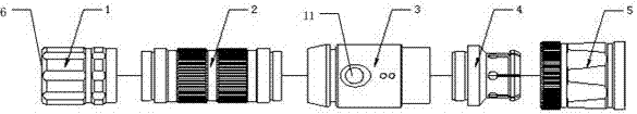
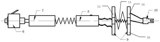
[0023] like Figure 1~Figure 3 As shown, a safety ignition device for electronic ignition without electric electrodes, which includes an external structure and an internal circuit structure, the external structure includes a rear seat 1, a battery cylinder 2, a middle switch part 3 and a locking part 5, The rear seat 1, the battery cartridge 2, the middle switch part 3 and the locking part 5 are installed in sequence with each other, and the locking part 5 is also installed in cooperation with the cartridge base 12 to lock or loosen the cartridge base 12, and the inside of the locking part 5 An intermediate connector 4 is provided, and the intermediate connector 4 is fitted in the locking part 4 and connected to the cartridge base 12; the internal circuit structure includes a...


PUM


Abstract

The invention discloses a safe igniting device applied to an electronic igniting non-electric welding rod. The device comprises an external structure and an internal circuit structure, wherein the external structure comprises a rear seat, a battery housing, an intermediate switch part and a locking part which are sequentially mounted in a mutual fitting manner; the locking part is mounted in match with a medicine barrel base and used for locking or releasing the medicine barrel base; an intermediate connecting part is arranged in the locking part in a fitting manner and is connected to the medicine barrel base; the internal circuit structure comprises a tail safety switch, a battery, an intermediate exciting switching device, an electrifying driving plate and a metal inserting part which are sequentially connected through circuits. The device has the beneficial effects of being convenient to dismount and mount, stable, reliable, and safe to use and store.

Description

technical field [0001] The invention relates to a safety ignition device, which belongs to the technical field of structure design and circuit design, in particular to a safety ignition device used for electronic ignition without electric welding rod. Background technique [0002] In order to solve the problem that traditional welding methods cannot be used under extreme special conditions such as high altitude, underground, and underwater, where energy supply is inconvenient, many scholars have devoted themselves to research in the field of non-electric welding electrodes and achieved some research results. For example, "patent ZL0810227057.X" proposes a manual thermal flux electrode, "patent ZL201210391069.2" proposes an electrode for electroless welding, "patent ZL201110126018.2" discloses a portable welding pen, and "patent ZL201210159201.7 "disclosed a simple electric-free welding pen, and "patent ZL200620024766.4" invented a pocket-type welding pen. The research focus...

Claims


Application Information

Patent Timeline
IPC IPC(8): B23K37/00B23K35/00
CPCB23K35/00B23K37/00
Inventor 温志高钟时雨高霆郭奇肖亚东
Owner CHENGDU GALAXY POWER CO LTD
Why Eureka
Try Eureka