
Taping mechanism and taping equipment

A glue sticking mechanism and tape technology, which is applied in the directions of sending objects, thin material handling, transportation and packaging, etc., can solve the problems of difficult to achieve automatic glue sticking, not strong enough bonding, and low operation efficiency.

Active Publication Date: 2021-01-22
GUANGZHOU MINHUI AUTOMOBILE PARTS
View PDF14 Cites 3 Cited by
  • Summary
  • Abstract
  • Description
  • Claims
  • Application Information

AI Technical Summary

Problems solved by technology

[0002] In the process of realizing the present invention, the inventor found that there are at least the following problems in the prior art. At present, many auto parts manufacturers use manual operations for the adhesive parts. Manual gluing operation is inefficient, such as the inner side of the car body door frame trim, because the gluing surface is curved, it is difficult to realize automatic gluing
The gluing surface of the workpiece is curved, and the gluing surface of the workpiece is uneven. For the current gluing equipment, it is difficult to control whether the uneven plane or curved surface can be pasted. Often, the tape is not pressed in place to form an empty bond or there is a problem. The bond is not under pressure, resulting in a bond that is not strong enough

Method used


Image

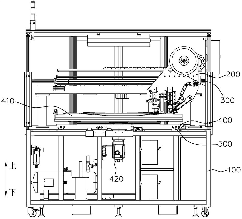
  • Taping mechanism and taping equipment
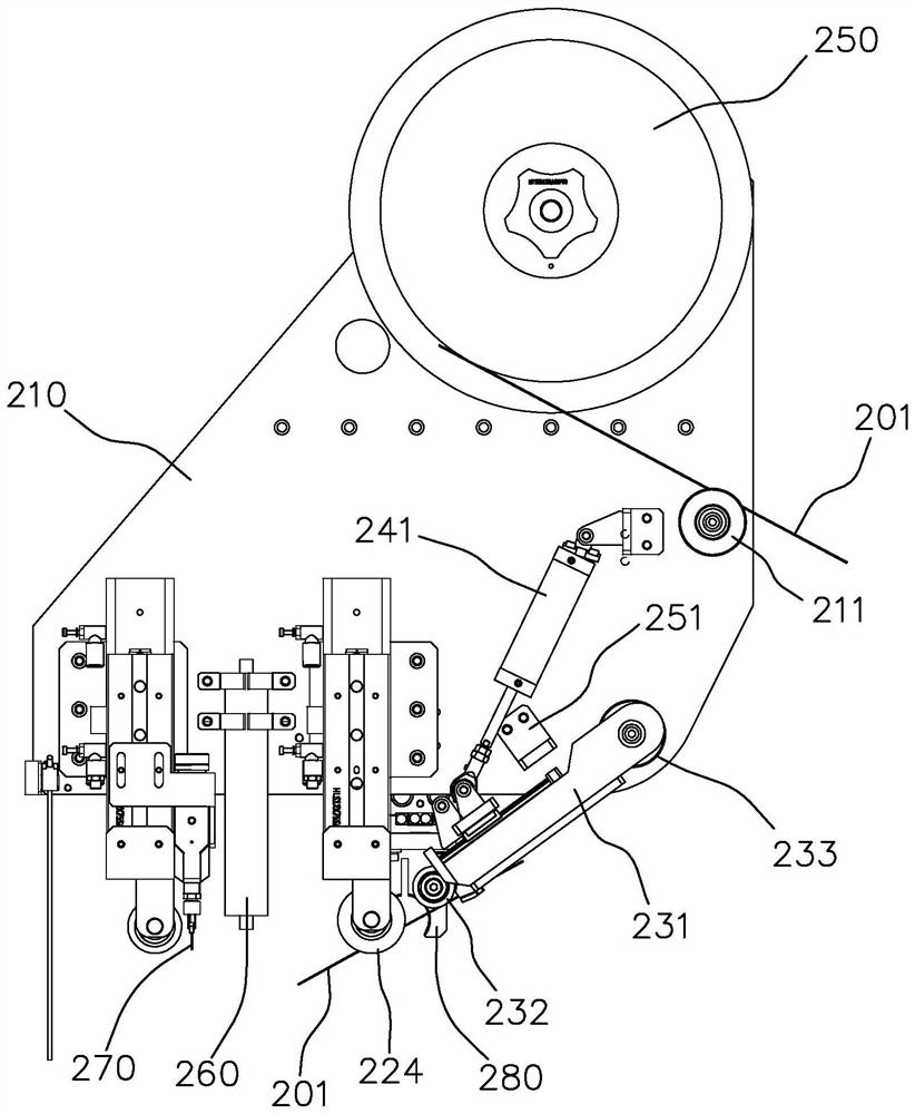
  • Taping mechanism and taping equipment
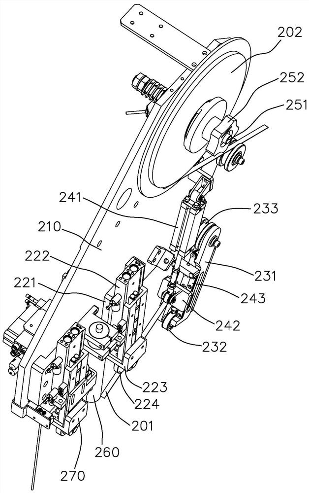
  • Taping mechanism and taping equipment

Examples


Embodiment Construction

[0021] This part will describe the specific embodiment of the present invention in detail, and the preferred embodiment of the present invention is shown in the accompanying drawings. Each technical feature and overall technical solution of the invention, but it should not be understood as a limitation on the protection scope of the present invention.

[0022] In the description of the present invention, it should be understood that the orientation descriptions, such as up, down, front, back, left, right, etc. indicated orientations or positional relationships are based on the orientations or positional relationships shown in the drawings, and are only In order to facilitate the description of the present invention and simplify the description, it does not indicate or imply that the device or element referred to must have a specific orientation, be constructed and operated in a specific orientation, and thus should not be construed as limiting the present invention.

[0023] I...


PUM


Abstract

The invention discloses a taping mechanism and taping equipment, and relates to the technical field of taping. The taping mechanism comprises a base plate; an adhesive tape carrying part used for carrying an adhesive tape roll; a compressing part which comprises a compressing seat, wherein one end of the compressing seat is hinged to the base plate, a first guide wheel is installed at the other end of the compressing seat, the first guide wheel presses the adhesive tape downwards to enable the adhesive tape to be tightly attached to a workpiece, a second guide wheel is installed at the end, hinged to the base plate, of the compressing seat, the compressing seat is hinged to the base plate through a rotating shaft, and the second guide wheel is installed on the rotating shaft; a connectingpart which comprises a telescopic connecting piece and a sliding seat hinged to the lower end of the connecting piece; a pressing wheel part which comprises a pressing wheel capable of moving up and down; and an adhesive tape shearing part which comprises a pair of scissors and is used for shearing the adhesive tape located on a passing path. The taping mechanism can avoid the situation that bonding is not firm enough after empty bonding is formed or bonding is not pressed due to the fact that the adhesive tape is not pressed in place.

Description

technical field [0001] The invention relates to the technical field of gluing, in particular to a gluing mechanism and also to gluing equipment. Background technique [0002] In the process of realizing the present invention, the inventor found that there are at least the following problems in the prior art. At present, many auto parts manufacturers use manual operations for the gluing part, and the manual gluing operation is inefficient, such as the door frame trim of the automobile body On the inner side, since the adhesive surface is curved, it is difficult to realize automatic adhesive application. The gluing surface of the workpiece is curved, and the gluing surface of the workpiece is uneven. For the current gluing equipment, it is difficult to control whether the uneven plane or curved surface can be pasted. Often, the tape is not pressed in place to form an empty bond or there is a problem. There is no pressure on the bond, resulting in a weak bond. Therefore, ther...

Claims


Application Information

Patent Timeline
IPC IPC(8): B65H35/07B65H35/00B65H37/04
CPCB65H35/06B65H35/0073B65H37/04Y02P70/50Y02E60/10
Inventor 王彦文
Owner GUANGZHOU MINHUI AUTOMOBILE PARTS
Learn More