Multi-angle adjustable cutting device for mechanical engineering manufacturing

A technology for mechanical engineering and cutting devices, applied in the field of multi-angle adjustable cutting devices used in mechanical engineering manufacturing, can solve the problems of inability to accurately adjust the limit device, premature failure of operators, affecting the cutting effect of the original, etc., to avoid accurate The effect of precision error and avoiding close contact with the tool

Inactive Publication Date: 2021-01-22
NINGBO POLYTECHNIC
View PDF1 Cites 3 Cited by
  • Summary
  • Abstract
  • Description
  • Claims
  • Application Information

AI Technical Summary

Problems solved by technology

[0006] 1. The cutter used for cutting the original is inconvenient to adjust at multiple angles, so that the cutter presents different angles to process the original;
[0007] 2. When the original is being processed and moving, the limit device of the original cannot be adjusted precisely under different cutting size requirements;
[0008] 3. During the cutting and moving process of the original, the cutting end of the original is likely to affect the cutting effect of the original due to the change of the stress point of the original;
[0009] 4. When the original is manually pushed for cutting, it is easy to cause premature damage to the operator when it is close to the cutting blade

Method used


Image

  • Multi-angle adjustable cutting device for mechanical engineering manufacturing
  • Multi-angle adjustable cutting device for mechanical engineering manufacturing
  • Multi-angle adjustable cutting device for mechanical engineering manufacturing

Examples


Embodiment Construction

[0034]The following will clearly and completely describe the technical solutions in the embodiments of the present invention with reference to the accompanying drawings in the embodiments of the present invention. Obviously, the described embodiments are only some of the embodiments of the present invention, not all of them. The components of the embodiments of the invention generally described and illustrated in the figures herein may be arranged and designed in a variety of different configurations. Accordingly, the following detailed description of the embodiments of the invention provided in the accompanying drawings is not intended to limit the scope of the claimed invention, but merely represents selected embodiments of the invention. Based on the embodiments of the present invention, all other embodiments obtained by those skilled in the art without making creative efforts belong to the protection scope of the present invention.

[0035] In describing the embodiments of...


PUM


Abstract

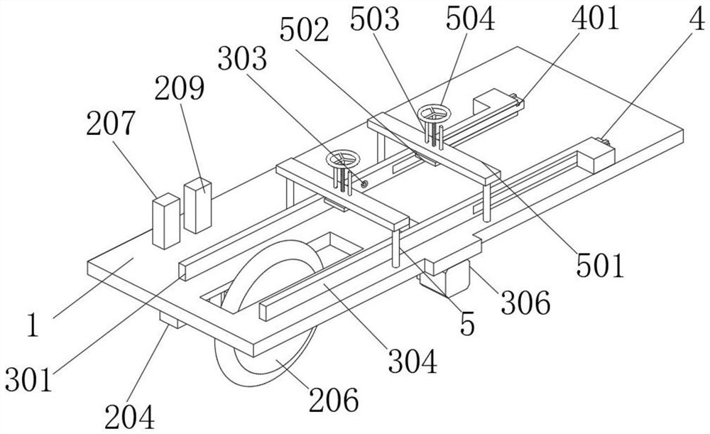
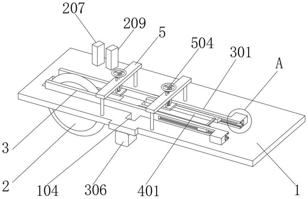
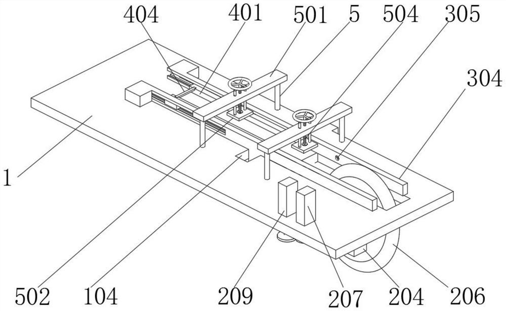
The invention discloses a multi-angle adjustable cutting device for mechanical engineering manufacturing. The multi-angle adjustable cutting device comprises a cutting plate, a cutting tool adjustingmechanism, a limiting adjusting mechanism, a pushing mechanism and a fixing mechanism; a cutting groove is formed in the cutting plate, and a first penetrating hole and a second penetrating hole are formed in one side of the cutting groove side by side; a first penetrating hole and a second penetrating hole are formed in the cutting plate, two limiting grooves are formed in one end of the cuttinggroove, and limiting grooves are formed in the cutting plate; and the cutting tool adjusting mechanism is arranged below the cutting plate, the limiting adjusting mechanism is arranged above the cutting plate, the pushing mechanism is installed on the limiting adjusting mechanism, the fixing mechanism is arranged on the outer side of the limiting adjusting mechanism, and the fixing mechanism is arranged on the upper surface of the cutting plate. The pushing mechanism is adopted for controlling the movement of the rear half section during raw material cutting, an operator is prevented from making contact with a cutter in a close distance, and the operator is protected.

Description

technical field [0001] The invention belongs to the technical field of mechanical engineering, and in particular relates to a multi-angle adjustable cutting device used in mechanical engineering manufacturing. Background technique [0002] Mechanical engineering is an engineering discipline that uses the laws of physics to analyze, design, manufacture and maintain mechanical systems. Mechanical engineering is based on related natural science and technical science, combined with technical experience in production practice, to study and solve problems in The applied discipline of all theoretical and practical issues in the development, design, manufacture, installation, operation and maintenance of various types of machinery. [0003] In the process of mechanical engineering manufacturing, it is necessary to process some mechanical originals. When cutting and processing mechanical originals, the existing cutting device generally uses a fixed mechanism to limit the processing o...

Claims


Application Information

Patent Timeline
Patent Type & Authority Applications(China)
IPC IPC(8): B23D19/00B23D35/00B23D33/02
CPCB23D19/00B23D33/02B23D35/007
Inventor 冯桂香商建方
Owner NINGBO POLYTECHNIC
Why Eureka
Try Eureka