
M iron lug plate forming device

A forming device and iron lug technology, which is applied in the field of electric poles, can solve the problems of restricting mass production of products, low processing precision, and high scrap rate, and achieve the effects of low scrap rate, high processing accuracy, and high bending tightness

Pending Publication Date: 2021-01-22
贵州长通集团智造有限公司
View PDF0 Cites 0 Cited by
  • Summary
  • Abstract
  • Description
  • Claims
  • Application Information

AI Technical Summary

Problems solved by technology

[0002] M iron is a non-standard product of electric non-standard iron accessories used to prevent the electric pole from slipping and distorting after fixing the cross arm. , requires mass production and fast production. There are two ear plates on the M iron. The current M iron ear plates are processed by manual bending, which has the problems of low efficiency, low processing accuracy and high scrap rate, which seriously restricts the large-scale production of this product. mass production

Method used


Image

  • M iron lug plate forming device
  • M iron lug plate forming device
  • M iron lug plate forming device

Examples


Embodiment 1

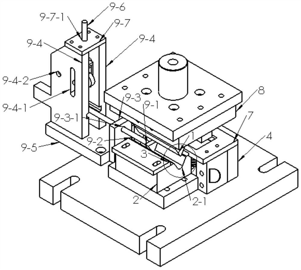
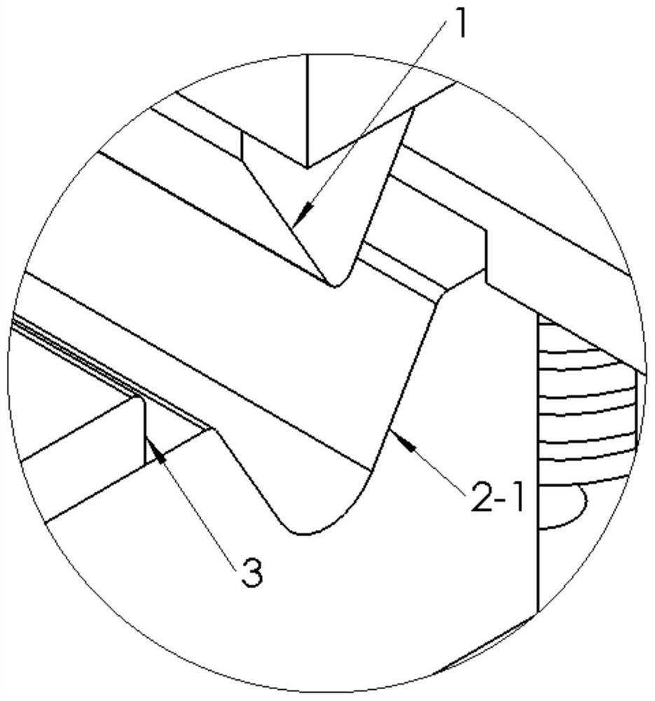
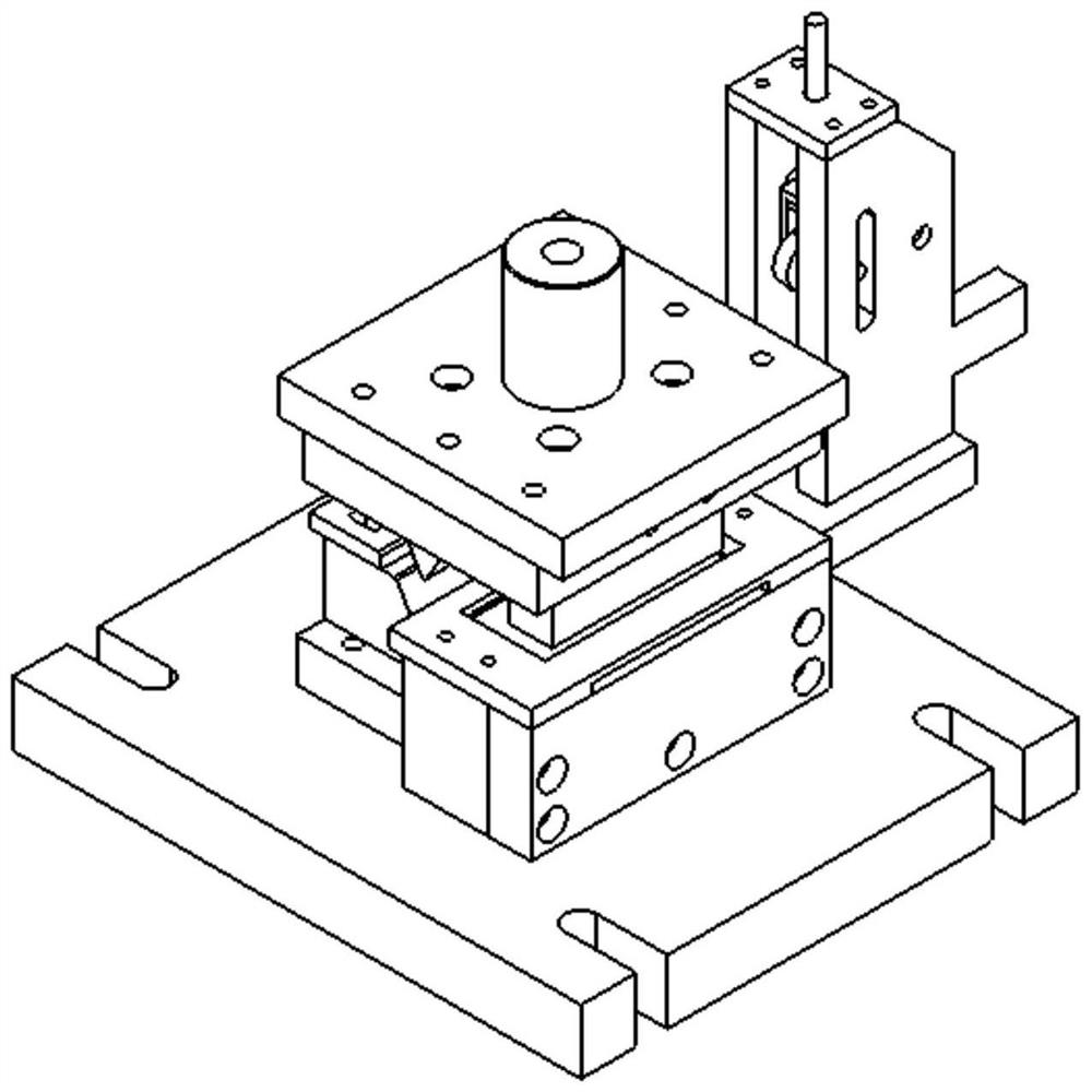
[0053] Example 1: Reference Figure 1 to Figure 8 , a M iron ear plate forming device, comprising: a bending upper die 1, the bending upper die 1 is a regular triangular prism cylinder, one side of the bending upper die 1 is perpendicular to the direction of movement of the bending upper die 1 , the length of the bottom side of the bending upper die 1 is 30mm, the side edge of the lower part of the bending upper die 1 is arc chamfering, and the radius of the arc chamfering is 2mm; the bending lower die 2 is set on the bending lower die 2 There is a groove 2-1, the groove 2-1 is a regular triangular prism, the groove 2-1 is located directly below the bending upper die 1, and one of the sides of the groove 2-1 is perpendicular to the movement direction of the bending upper die 1, The length of the bottom surface of the groove 2-1 is 35mm, the side edge of the lower part of the groove 2-1 is arc chamfered, the radius of the arc chamfer is 8mm, the intersection line between the gr...


PUM


Abstract

The invention discloses an M iron lug plate forming device. The M iron lug plate forming device comprises an upper bending die and a lower bending die, wherein the upper bending die is a regular triangular prism cylinder, one side surface of the upper bending die is perpendicular to the moving direction of the bending upper die, the side length of the bottom surface of the upper bending die is 30mm, the chamfered edge of the lower part of the upper bending die is an arc chamfer, and the radius of the arc chamfer is 2 mm; and a groove is formed in the lower bending die, the groove is in a regular triangular prism shape and located under the lower bending die, one side surface of the groove is perpendicular to the moving direction of the upper bending die, the side length of the bottom surface of the groove is 35 mm, the chamfered edge of the lower part of the groove is an arc chamfer, the radius of the arc chamfer is 8 mm, and the intersecting line chamfer of the groove and the upper surface of the upper bending die is 2 mm. The M iron lug plate forming device aims to solve problems of low efficiency, low machining precision and high rejection rate in the prior art.

Description

technical field [0001] The invention relates to the technical field of electric poles, in particular to an M iron lug forming device. Background technique [0002] M iron is a non-standard product of electric non-standard iron accessories used to prevent the electric pole from slipping and distorting after fixing the cross arm. , requires mass production and fast production. There are two ear plates on the M iron. The current M iron ear plates are processed by manual bending, which has the problems of low efficiency, low processing accuracy and high scrap rate, which seriously restricts the large-scale production of this product. Mass production. Contents of the invention [0003] In order to solve the above shortcomings and deficiencies of the prior art, the object of the present invention is to provide a M iron lug forming device. [0004] The technical solution of the present invention is: a kind of M iron lug forming device, comprising: [0005] Bending upper die, s...

Claims


Application Information

Patent Timeline
IPC IPC(8): B21D35/00B21D11/10B21D11/22B21D28/02B21D28/04B21D28/14B21D37/08B21D43/00B21D43/02B21D45/04
CPCB21D11/10B21D11/22B21D28/02B21D28/04B21D28/14B21D35/002B21D37/08B21D43/003B21D43/02B21D45/04
Inventor 夏军尚跃立廖佳
Owner 贵州长通集团智造有限公司
Learn More