
Bending machine with combined clamping mechanism

A technology of clamping mechanism and bending machine, which is applied in the field of bending machine, can solve the problems of complex operation and unsuitability for small workshops, and achieve the effects of low cost, concise bending action and simple mechanism

Inactive Publication Date: 2019-03-15
南京苏格信息技术有限公司
View PDF0 Cites 0 Cited by
  • Summary
  • Abstract
  • Description
  • Claims
  • Application Information

AI Technical Summary

Problems solved by technology

[0002] The bending machine is a machine capable of bending thin plates. Its structure mainly includes a bracket, a workbench and a clamping plate. The workbench is placed on the bracket. The workbench is composed of a base and a pressure plate. Connected, generally using electromagnetic force clamping, so that the pressure plate can be made into a variety of workpiece requirements, and can process workpieces with side walls, and the operation is very simple, but its operation is more complicated, not suitable for small workshops

Method used


Image

  • Bending machine with combined clamping mechanism

Examples


Embodiment Construction

[0010] The present invention will be further described below in conjunction with the embodiments and with reference to the accompanying drawings. It should be understood that the following specific embodiments are only used to illustrate the present invention and are not intended to limit the scope of the present invention. It should be noted that the words "front", "rear", "left", "right", "upper" and "lower" used in the following description refer to the direction in the figure, and the words "inner" and "outer ” refer to directions towards or away from the geometric center of a particular part, respectively.

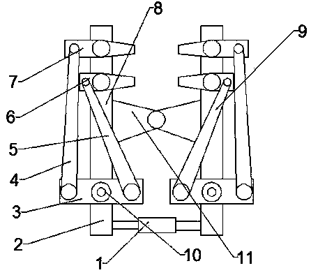
[0011] Such as figure 1 The shown bending machine with a combined clamping mechanism includes a left clamping mechanism 8, the left clamping mechanism 8 includes a support plate 2, the lower end of the support plate 2 is connected with a rotating plate 3, and the The middle part of the rotating plate 3 is connected with the steering gear 10 , the right end of the rot...


PUM


Abstract

The invention discloses a bending machine with a combined clamping mechanism. The bending machine comprises a left clamping mechanism, wherein the left clamping mechanism comprises a supporting plate;the lower end of the supporting plate is connected with a rotary plate; the middle part of the rotary plate is connected with a steering engine; the right end of the rotary plate is connected with afirst connecting rod; the upper end of the first connecting rod is connected with a lower clamping plate; the right end of the rotary plate is connected with a second connecting rod; the tail end of the second connecting rod is connected with an upper clamping plate; the right side of the left clamping mechanism is equipped with a right clamping mechanism; the right clamping mechanism and the leftclamping mechanism are the same in structure; the middle part of the clamping mechanism is fixedly connected with a connecting plate; and the tail end of the supporting plate of the clamping mechanism is connected with an air cylinder. The bending machine is simple and quick in bending action, is simple in structure, is low in manufacturing cost, and is suitable for being used in a small-sized plant.

Description

technical field [0001] The invention relates to a bending machine, in particular to a bending machine with a combined clamping mechanism. Background technique [0002] The bending machine is a machine capable of bending thin plates. Its structure mainly includes a bracket, a workbench and a clamping plate. The workbench is placed on the bracket. The workbench is composed of a base and a pressure plate. Connected, generally using electromagnetic force clamping, so that the pressure plate can be made into a variety of workpiece requirements, and can process workpieces with side walls, and the operation is very simple, but its operation is more complicated, not suitable for small workshops. Contents of the invention [0003] The purpose of the present invention is to solve the above problems and propose a bending machine with a combined clamping mechanism. [0004] In order to achieve the above object, the method adopted by the present invention is a bending machine with a c...

Claims


Application Information

Patent Timeline
Patent Type & Authority Applications(China)
IPC IPC(8): B21D5/04B21D43/00
CPCB21D5/04B21D43/003
Inventor 吴娜娜
Owner 南京苏格信息技术有限公司
Learn More