
Cerebrospinal fluid drainage tube and cerebrospinal fluid drainage device

A cerebrospinal fluid and drainage tube technology, applied in the field of medical devices, can solve the problems of prone to intracranial pressure and increase, and achieve the effect of reducing the risk of increased intracranial pressure

Pending Publication Date: 2021-01-22
SHINEYARD MEDICAL DEVICE CO LTD
View PDF0 Cites 1 Cited by
  • Summary
  • Abstract
  • Description
  • Claims
  • Application Information

AI Technical Summary

Problems solved by technology

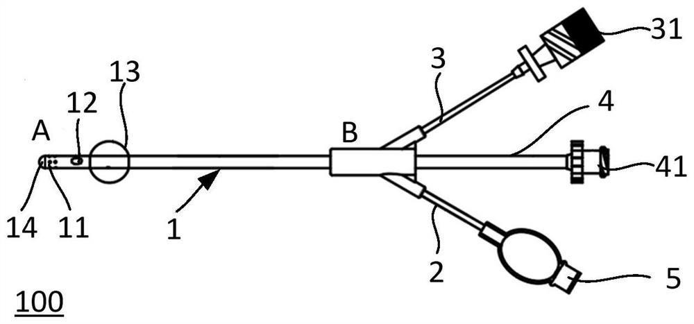
[0005] The purpose of the present invention is to provide a cerebrospinal fluid drainage tube and a cerebrospinal fluid drainage device, aiming to provide a device for continuous drug injection and drainage, so as to solve the technical problem that intracranial pressure is prone to rise during cerebrospinal fluid drainage treatment

Method used


Image

  • Cerebrospinal fluid drainage tube and cerebrospinal fluid drainage device
  • Cerebrospinal fluid drainage tube and cerebrospinal fluid drainage device
  • Cerebrospinal fluid drainage tube and cerebrospinal fluid drainage device

Examples


Embodiment Construction

[0026] In order to make the object, technical solution and advantages of the present invention clearer, the present invention will be further described in detail below in conjunction with the accompanying drawings, that is, embodiments. It should be understood that the specific embodiments described here are only used to explain the present invention, not to limit the present invention.

[0027] It should be noted that when a component is referred to as being “fixed on” or “disposed on” another component, it may be directly or indirectly on the other component. When an element is referred to as being "connected to" another element, it can be directly or indirectly connected to the other element. The orientation or positional relationship indicated by the terms "upper", "lower", "left", "right", etc. are based on the orientation or positional relationship shown in the drawings, and are for convenience of description only, rather than indicating or implying the referred device ...


PUM


Abstract

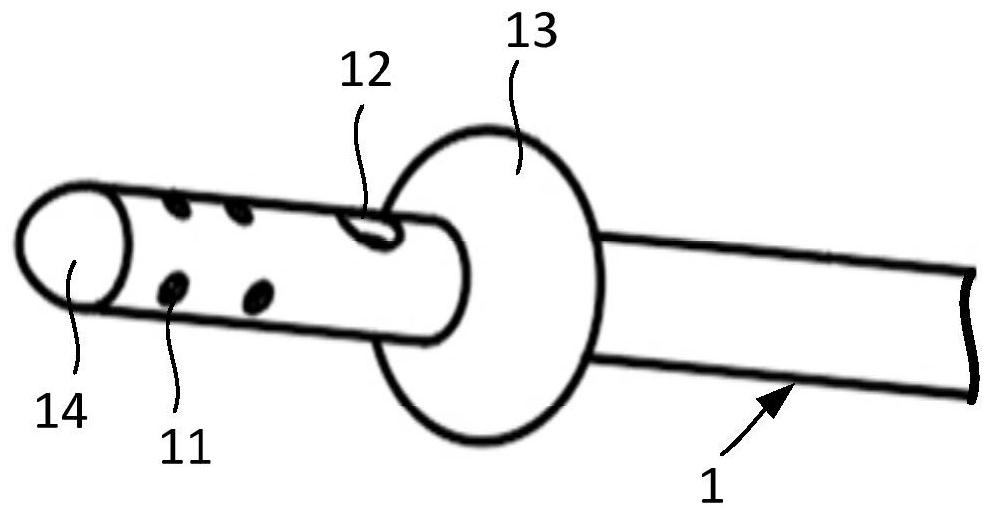
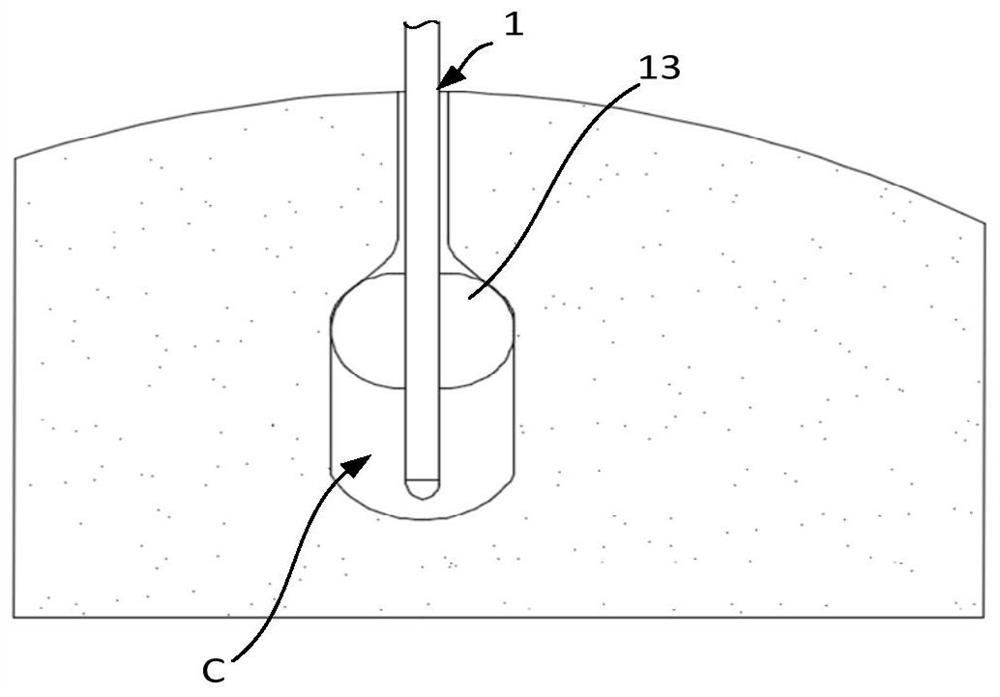
The invention relates to the technical field of medical appliances and discloses a cerebrospinal fluid drainage tube and a cerebrospinal fluid drainage device. The cerebrospinal fluid drainage tube isused for solving the technical problem of related technologies that rise of intracranial pressure is easily caused during cerebrospinal medicine injection drainage. The cerebrospinal fluid drainage tube comprises a main tube, wherein a medicine injection chamber, a drainage chamber and a diversion chamber are arranged in the main tube in a spaced manner, the main tube comprises a drainage end anda connecting end, the drainage end is provided with a medicine injection hole communicating with the medicine injection chamber and a drain hole communicating with the drainage chamber, elastic support parts communicating with the diversion chamber are arranged on the main tube close to positions of the medicine injection hole and the drain hole, and diameters of the elastic support parts after charged inflation are greater than a tube diameter of the main tube. The cerebrospinal fluid drainage tube and the cerebrospinal fluid drainage device can be applied to cerebral surgical operations.

Description

technical field [0001] The invention relates to the technical field of medical devices, in particular to a cerebrospinal fluid drainage tube and a cerebrospinal fluid drainage device. Background technique [0002] External drainage of cerebrospinal fluid is one of the most commonly used clinical treatment techniques in neurosurgery. It specifically refers to the continuous drainage of cerebrospinal fluid in the ventricle or lumbar cistern to the closed system outside the body, including ventricular drainage and lumbar cistern drainage. The main purposes of external ventricular drainage include release of contaminated cerebrospinal fluid, monitoring and control of intracranial pressure, and administration of necessary medications. [0003] Among them, in the clinical practice of drug treatment, the drug needs to be injected into the brain first, and then sucked out after the drug is absorbed and reacted. In related technologies, a double-lumen tube with a drainage cavity and...

Claims


Application Information

Patent Timeline
Patent Type & Authority Applications(China)
IPC IPC(8): A61M27/00
CPCA61M27/006
Inventor 张世忠汪郁卉许宗兰
Owner SHINEYARD MEDICAL DEVICE CO LTD
Learn More