Centrifugal water pump built-in booster device

A technology of centrifugal water pump and booster device, which is applied to components, pumps, piston pumps, etc. of the pumping device used for elastic fluid, and can solve the problems of poor boosting effect, unsatisfactory sealing and poor control and other issues to achieve the effect of improving sealing, ensuring work efficiency and work economic benefits

Active Publication Date: 2022-03-25
东莞市深鹏电子有限公司
View PDF7 Cites 0 Cited by
  • Summary
  • Abstract
  • Description
  • Claims
  • Application Information

AI Technical Summary

Problems solved by technology

[0003] When the centrifugal water pump in the prior art is working, it usually needs to adjust its pumping speed according to the actual pumping situation. In the prior art, the rotation speed of the impeller is usually controlled by controlling the rotation of the pump shaft driven by the motor, and then the pumping speed is adjusted. In the prior art, the pressure in the inner cavity of the centrifugal water pump cannot be well controlled, especially for the boosting work, which cannot be well controlled, and as the boosting work is carried out, the pressure in the pump body Sealing requirements will be improved, often when boosting work, the seal in the pump body cannot meet the requirements, and the boosting effect is poor, and the pumping work of the centrifugal water pump cannot be controlled accordingly according to the actual situation, and the boosting work cannot be carried out normally. Reduce the working efficiency of the centrifugal water pump and reduce the economic benefits. Therefore, the present invention proposes a built-in booster device for the centrifugal water pump to solve the above problems

Method used


Image

  • Centrifugal water pump built-in booster device
  • Centrifugal water pump built-in booster device
  • Centrifugal water pump built-in booster device

Examples


Embodiment Construction

[0025] The technical solutions in the embodiments of the present invention will be clearly and completely described below. The embodiments of the present invention, and all other embodiments obtained by those of ordinary skill in the art without creative work, fall within the protection scope of the present invention.

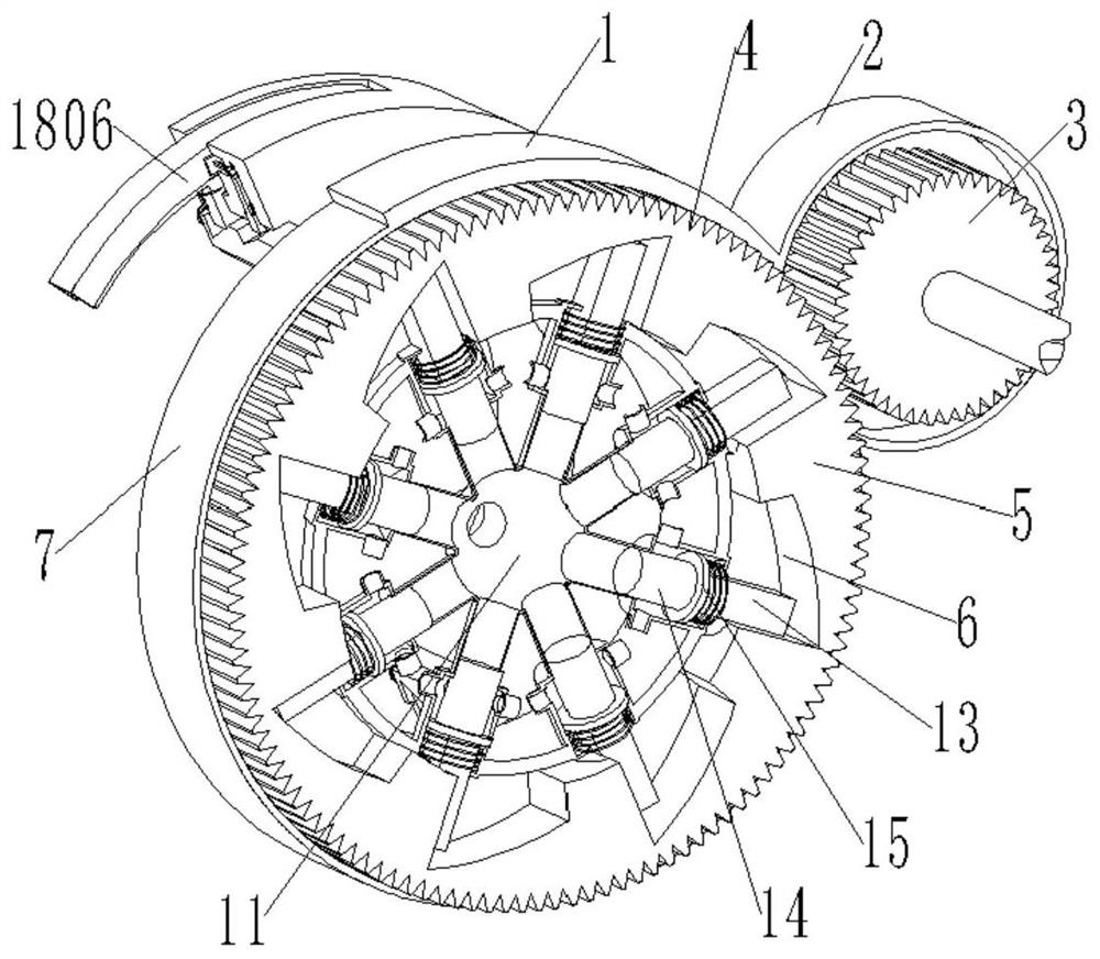
[0026] see figure see Figure 1 to Figure 7 , the present invention provides a technical solution: a built-in booster device for a centrifugal water pump, the present invention includes a centrifugal water pump body 1, a placing box 2, a first gas compression pipe 8, a second gas compression pipe 9, a gas compression ball 11 and a seal boost auxiliary mechanism 18;

[0027] One side of the main body 1 of the centrifugal water pump is integrally formed with a placing box 2, a rotating shaft is inserted in the placing box 2, one end of the rotating shaft is connected with a rotating gear 3, and the other end is connected with a reducer, and the reducer is arrang...


PUM


Abstract

The invention discloses a built-in pressure boosting device of a centrifugal water pump. When the centrifugal water pump is boosted, the first gas compression tube, the second gas compression tube and the air compression ball provided in the invention can control the impeller side of the centrifugal water pump. The vacuum low-pressure area at the side position is compressed, and then the pressure of the low-pressure area can be boosted, and as the pressure gradually increases, the seal in the inner cavity of the centrifugal water pump can be improved through the set booster auxiliary mechanism. To ensure that the sealing strength in the inner cavity of the centrifugal water pump can meet the increase of pressure, so that the problem of air leakage will not be caused by the increase of pressure, thereby ensuring the normal operation of the boosting work, ensuring the working efficiency and working efficiency of the centrifugal water pump economic benefits.

Description

technical field [0001] The invention relates to the technical field of centrifugal water pump equipment, in particular to a built-in booster device for a centrifugal water pump. Background technique [0002] Centrifugal water pump is referred to as "centrifugal pump"; it is a pumping machine that utilizes the centrifugal motion of water; it consists of a pump casing, an impeller, a pump shaft, a pump frame, etc.; The impeller drives the water in the pump to rotate at a high speed, the water moves centrifugally, and is thrown out and pressed into the water outlet pipe; after the water is thrown out, the pressure near the impeller decreases, and a low pressure area is formed near the rotating shaft; the pressure ratio here The atmospheric pressure is much lower, and the water outside is under the action of atmospheric pressure, and the bottom valve is flushed and enters the pump from the water inlet pipe; the flushed water is thrown out during the high-speed rotation of the im...

Claims


Application Information

Patent Timeline
Patent Type & Authority Patents(China)
IPC IPC(8): F04D29/00F04D29/08F04B27/047F04B35/04F04B39/12
CPCF04D29/007F04D29/086F04B35/04F04B39/123F04B27/047F04B27/0404
Inventor 陈鑫淑
Owner 东莞市深鹏电子有限公司
Why Eureka
Try Eureka